
 WhatsApp: +86 16626708626
 Email:
  Phone: +86 16626708626
Description
Key Technical Specifications
| Parameter | Value |
| System Compatibility | Bently Nevada 3500/05 Mainframe Racks |
| Termination Variant | Internal Terminations (Supports direct rear I/O card mounting) |
| Layer Count | Multi-layer heavy copper PCB for high noise immunity |
| Data Bus Connectivity | Dedicated TDM (Time Division Multiplex) bus lines |
| Power Bus Routing | Dual-redundant power distribution traces |
| Operating Temperature | −30 to +65 °C (−22 to +150 °F) |
| Storage Temperature | −40 to +85 °C (−40 to +185 °F) |
| Humidity Resistance | 95% non-condensing relative humidity |
Product Introduction & Supply Chain Strategy
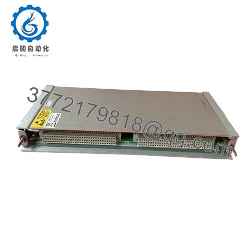
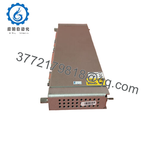
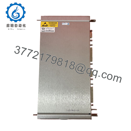
The Bently Nevada 125712-01 is the internal termination mainframe backplane board for the 3500/05 Machinery Protection Rack. Acting as the physical and electrical backbone of the entire monitoring system, this multi-layer circuit board routes high-speed data buses, power rails, and sensor signals between the front-mounted monitor modules and the rear-mounted I/O cards. It handles the critical communications required for real-time machine protection, ensuring that data synchronization across slots remains glitch-free.
From a supply chain perspective, stocking a 125712-01 as a New Surplus spare is an essential high-level insurance strategy. While individual monitor cards fail more frequently, a catastrophic backplane failure—often caused by severe ground loops, lightning strikes, or physical pin damage—blinds the entire 3500 system at once. This forces an immediate emergency plant shutdown for all interlocked machinery. Maintaining a factory-sealed new surplus backplane eliminates standard OEM factory lead times and ensures your site is protected against total monitoring blackouts. It also circumvents the extreme risks of refurbished backplanes, which frequently hide microscopic hairline fractures or degraded trace insulation that cause intermittent communication drops.

- 125712-01
Installation & Configuration Guide
Stage 1: Pre-Installation (Prep & Safety)
- Complete a comprehensive lock-out/tag-out (LOTO) process to fully isolate all AC/DC power sources feeding the target 3500 rack.
- Fasten a grounded static-dissipative wrist strap to your arm and attach it to the bare metal cabinet frame ground.
- Label and disconnect every single field terminal wire, communication cable, and grounding wire connected to the front and rear of the rack.
- Remove all front modules (Power Supplies, Rack Interface Module, Monitors) and rear I/O cards. Store them in individual anti-static bags.
Stage 2: Removal
- Unbolt the 3500/05 chassis from the control panel or 19-inch electronic enclosure.
- Remove the rear sheet metal protection covers to gain access to the backplane assembly fasteners.
- Systematically loosen and extract the mounting screws holding the 125712-01 PCB to the aluminum chassis frame.
- Carefully lift the board away from the frame structure, taking great care not to strike or bend any of the exposed male connector pins on either side of the board.
Stage 3: Installation (Clone & Seat)
- Unpack the new surplus 125712-01 backplane on an ESD-safe workbench.
- Carefully check that the model and revision levels match the old unit precisely.
- Position the new backplane over the chassis mounting standoffs. Hand-start all retaining screws to avoid cross-threading.
- Tighten the screws using an alternating cross-pattern sequence to ensure even pressure across the PCB, preventing internal board stress or warping.
Stage 4: Power-On & Testing
- Re-install the rack frame into the cabinet enclosure and rebuild the module lineup by sliding the original power supplies and monitor modules back into their assigned slots.
- Re-attach the rear I/O modules and secure all terminal blocks.
- Re-energize the primary and secondary power supply lines. Observe the power supply LEDs; they must show steady green lines without clicking or fault indicators.
- Connect via 3500 Configuration Software to run a full rack self-test, verifying that every slot registers valid data bus communication across the new backplane.
Firmware/Software Versions & Upgrade Notes
The 125712-01 backplane is a passive electronic routing assembly and does not contain integrated firmware chips or microcontrollers. It does not require code flashes or software profile installations.
However, because this backplane establishes the physical bus lines for the Time Division Multiplexing (TDM) architecture, you must ensure that your existing Rack Interface Module (3500/22M) firmware is updated to a stable, identical version when putting the rack back online. If the backplane replacement was prompted by a severe system-wide electrical fault, verify that the configuration profile saved in the 3500 software matches the original node address settings before attempting to download the logic to the rack.
Frequently Asked Questions (FAQ)
What is the difference between an internal termination backplane like the 125712-01 and an external termination version?
The 125712-01 internal termination backplane is designed for standard setups where the rear I/O modules plug directly into the backplane, allowing field wiring to connect to terminal blocks located right on the back of the rack. External termination setups use a completely different backplane type that connects via multi-conductor cables to external terminal blocks mounted elsewhere in the cabinet.
Why shouldn’t we buy a refurbished backplane to save on maintenance costs?
Backplanes are complex, multi-layer circuit boards that route heavy currents and high-speed data across hundreds of individual traces. Refurbished backplanes often have underlying issues like heat-stressed copper layers, micro-cracks from structural flexing, or bent connector pins that have been manually straightened. These defects can easily cause intermittent communication losses or power bus shorts, risking a complete shutdown of all machinery monitored by the rack.
Can this backplane be replaced while some of the monitors in the rack stay online?
No. The backplane cannot be hot-swapped or serviced while the system is energized. Replacing the 125712-01 requires a complete power-down of the entire rack, the removal of all modules, and complete disconnection of all field wiring. This task must always be scheduled during a planned maintenance outage or plant turnaround.
Does this backplane include the aluminum 3500 housing rack frame?
No, the 125712-01 part number refers specifically to the backplane Printed Circuit Board (PCB) assembly complete with its array of slot connectors. It is sold as a drop-in replacement board for your existing 3500/05 chassis frame.
Are the connectors on this backplane board prone to pin wear?
Under normal operating conditions inside a cabinet, the connectors are highly stable. Pin damage typically occurs when heavy front modules or rear I/O cards are slammed into the rack unevenly or without proper alignment. Purchasing a New Surplus unit ensures that all connector housings and internal gold-plated pin sleeves are in factory-perfect condition, providing low contact resistance and solid connections.


