
 WhatsApp: +86 16626708626
 Email:
  Phone: +86 16626708626
Description
3. Key Technical Specifications
| Parameter | Value |
|---|---|
| Product Type | Four-Channel I/O Module |
| Part Number | 132417-01 |
| Series | Bently Nevada 3500 Machinery Protection System |
| Installation | Rear I/O Module |
| Channel Capacity | Four Channels |
| Primary Function | Field signal interface for compatible monitor |
| Rack Compatibility | Bently Nevada 3500 Rack |
| Connection Method | Rack backplane with rear field wiring terminals |
| Power Source | Supplied through rack backplane |
| Operating Temperature | Refer to associated 3500 rack environmental specifications |
| Construction | Industrial PCB with shielded signal interface |
| Typical Application | Turbines, Compressors, Pumps, Generators, Rotating Equipment |
Compatibility Note: The 132417-01 is a rear I/O module intended for specific four-channel monitoring applications within the Bently Nevada 3500 platform. It must be matched with the correct front monitor and I/O option. Ordering by part number alone without confirming the associated monitor can lead to installation issues.
4. Product Introduction
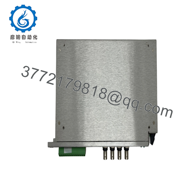
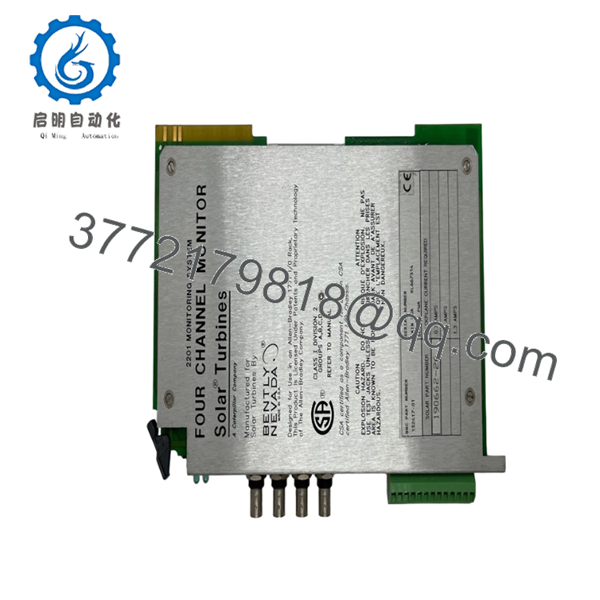
The Bently Nevada 132417-01 is a rear-mounted Four-Channel I/O Module used in the 3500 Machinery Protection System. It provides the electrical interface between field sensors and the corresponding front monitor, routing vibration or process signals through the rack backplane for continuous machinery protection.
Although it contains no measurement logic itself, the I/O module is essential to overall system performance. Proper selection of the matching rear I/O assembly ensures signal integrity, correct terminal assignments, and compatibility with the installed monitor module.

- 132417-01
- 132417-01
5. Installation & Configuration Guide
Stage 1 — Pre-Installation Preparation (10 Minutes)
⚠️ Safety First
- Notify operations of the planned maintenance window.
- Verify the protected machine is in a safe operating condition.
- Apply Lock-Out/Tag-Out (LOTO).
- Remove power from the 3500 rack.
- Wait at least 5 minutes for stored energy to discharge.
Tools Required
- Grounded ESD wrist strap
- PH1 screwdriver
- Fluke 115 multimeter
- Wire identification labels
- Smartphone for wiring photos
- Laptop with 3500 Configuration Software
Data Backup
- Export the rack configuration.
- Record the installed monitor model.
- Photograph all rear terminal wiring.
- Record firmware revision of the associated front monitor.
Stage 2 — Removing the Existing Module (5 Minutes)
- Remove the rear protective cover if fitted.
- Label every field cable before disconnecting.
- Loosen terminal connections carefully.
- Release the retaining hardware.
- Pull the I/O module straight out to avoid damaging the backplane connector.
Inspect for:
- Bent connector pins
- Loose terminals
- Corrosion
- Dust buildup
⚠️ Retain the original module until the replacement completes all functional tests.
Stage 3 — Installing the New Module (10 Minutes)
- Wear a grounded ESD wrist strap.
- Verify the replacement part number is 132417-01.
- Confirm compatibility with the installed four-channel front monitor.
- Insert the module evenly into the rear connector.
- Secure the retaining hardware.
- Reconnect all field wiring according to the recorded documentation.
Self-Checklist
- ☑ Part number confirmed
- ☑ Correct monitor matched
- ☑ Wiring restored
- ☑ Connector fully seated
- ☑ Mounting hardware secured
Stage 4 — Power-On & Functional Testing (15 Minutes)
Pre-Power Checks
- Measure rack supply voltage.
- Inspect wiring for shorts or loose terminals.
- Verify all connectors are fully engaged.
Startup Procedure
- Apply power to the 3500 rack.
- Observe normal startup indications.
- Connect using 3500 Configuration Software.
- Verify communication with the associated monitor.
- Confirm all four channels report healthy status.
- Perform signal simulation or sensor verification where practical.
- Review diagnostics and event logs.
⚠️ Troubleshooting Notes
Monitor Does Not Detect Inputs
- Incorrect rear I/O module installed
- Loose field wiring
- Connector not fully seated
- Incorrect monitor configuration
Intermittent Signals
- Shield grounding problem
- Damaged field cable
- High electromagnetic interference
- Loose terminal screws
Engineer’s Installation Notes
One mistake I’ve encountered during shutdowns is technicians replacing only the front monitor while assuming every rear I/O module is interchangeable. The 3500 platform uses multiple rear I/O variants that may have different terminal layouts and signal routing. Always verify the complete monitor and I/O assembly before ordering replacement parts.
Another recommendation is to photograph every terminal before removal. Even with wire markers, detailed photos often prevent wiring errors during reassembly, especially when multiple four-channel monitors are installed in the same rack. Keeping the original module available until commissioning is complete provides a reliable reference if unexpected communication or signal issues arise.
6. Frequently Asked Questions (FAQ)
Q1. What is the function of the 132417-01?
The 132417-01 is a rear Four-Channel I/O Module that provides the field wiring interface for a compatible Bently Nevada 3500 monitor. It routes sensor signals between field devices and the front monitoring module.
Q2. Can I replace only the rear I/O module?
Yes, provided the replacement has the exact same part number and matches the installed front monitor. Replacing it with an incompatible I/O version may prevent proper operation.
Q3. Does this module contain monitoring logic?
No. Signal processing and protection functions are performed by the front monitor. The 132417-01 serves as the electrical interface for field connections and signal routing.
Q4. Is 132417-01 still available?
The part is generally available through industrial automation suppliers as new surplus, refurbished, or tested used inventory. Availability depends on stock levels because many 3500 system components are now supplied through aftermarket channels rather than current OEM production.
Q5. Why should I verify the associated monitor before ordering?
Several Bently Nevada monitors use different rear I/O assemblies. Matching only the rack or series number is not sufficient. Confirm both the front monitor model and the rear I/O part number to avoid connector or wiring incompatibilities.
Q6. What inspections should a supplier perform before shipment?
A qualified supplier should complete:
- OEM part number and serial number verification
- Anti-counterfeit inspection
- Visual inspection for corrosion, scratches, or repair marks
- Connector and terminal integrity inspection
- Functional testing with a compatible 3500 rack
- Signal path verification
- Insulation resistance testing (>10 MΩ)
- ESD-safe packaging with QC sign-off
Requesting a functional test report or inspection photos before shipment is a practical way to reduce installation risk and minimize unplanned downtime.



