
 WhatsApp: +86 16626708626
 Email:
  Phone: +86 16626708626
Description
Key Technical Specifications
| Parameter | Value |
|---|---|
| Manufacturer | Bently Nevada |
| Part Number | 133323-01 |
| Product Family | 3500 Machinery Protection System |
| Associated Module | 3500/92 Communication Gateway |
| I/O Module Type | Modbus RS485 |
| Full Ordering Configuration | 3500/92-02-01-00 |
| I/O Type Code | 02 — Modbus RS485 |
| Memory Type | 01 — Low Memory |
| Agency Approval Code | 00 — None |
| Communication Protocol | Modicon Modbus / Modbus RTU |
| Physical Interface | RS485 |
| Data Access | Rack monitored values and status information |
| Configuration Software | 3500 Rack Configuration Software |
| Data Acquisition | 3500 Data Acquisition Software |
| Typical Power Consumption | 5.6 W |
| Operating Temperature | 0 to +65 °C |
| Storage Temperature | -40 to +85 °C |
| Humidity | Up to 95%, non-condensing |
| Approx. Dimensions | 24.2 × 10 × 2.5 cm |
| Approx. Weight | 0.4–0.5 kg |
| Installation | 3500 rack / 3500/92 communication gateway |
The OEM 3500/92 datasheet lists 133323-01 alongside the other 3500/92 communication options and explicitly identifies it as the ModbusRS485 I/O Module. The same documentation distinguishes it from 125736-01, 136188-01, and 136188-02, which use different communication interfaces.
Product Introduction
The Bently Nevada 133323-01 is the Modbus RS485 I/O module used with the 3500/92 Communication Gateway in a 3500 Machinery Protection System. It provides a serial Modbus interface for transferring monitored rack information to external PLC, DCS, SCADA, or other supervisory systems.
The part number matters because the 3500/92 uses different I/O modules for RS232/RS422, RS485, and Ethernet configurations. 133323-01 is specifically the RS485 variant, so it should not be ordered solely by the generic “3500/92 communication module” description.
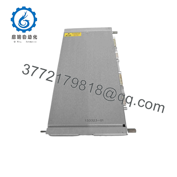
133323-01
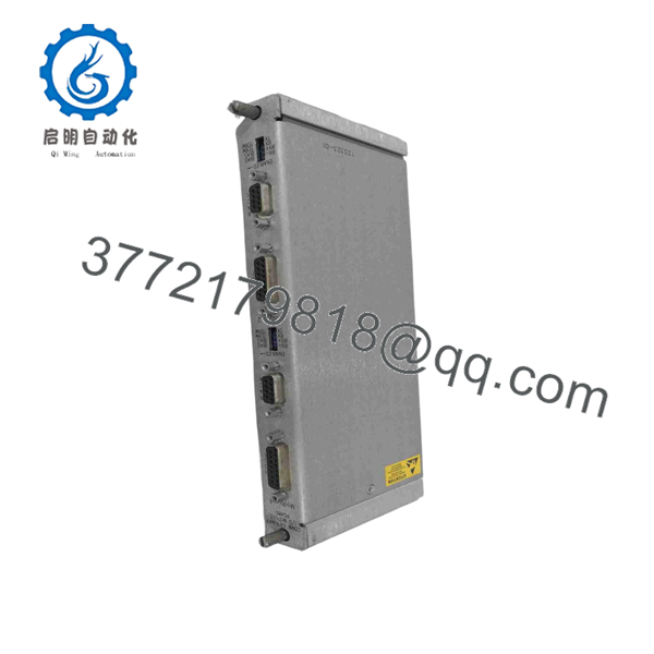
133323-01
Installation & Configuration Guide
Stage 1: Pre-Installation Preparation
Estimated time: 5–8 minutes
⚠️ Safety First: Confirm the maintenance window with operations. Place the machinery protection system in an approved maintenance state and follow the site’s lockout/tagout procedure where the installation exposes energized electrical circuits.
Tools Required
- ESD wrist strap
- Appropriate screwdriver
- Digital multimeter
- Wire labels
- Smartphone or camera
- Existing 3500 rack documentation
Data Backup
- Record the existing 3500/92 configuration.
- Photograph the front and rear module arrangement.
- Record the Modbus slave/node address.
- Record baud rate, parity, stop-bit, and other serial settings.
- Record the host PLC/DCS communication settings.
- Photograph terminal wiring before disconnecting anything.
- Record the existing firmware/configuration information where accessible.
⚠️ Do not change the Modbus settings during a routine hardware replacement unless the original configuration is unavailable or known to be incorrect.
Stage 2: Removing the Old Module
Estimated time: 5 minutes
- Place the rack in the approved maintenance condition.
- Identify the installed 3500/92 communication gateway.
- Verify that the failed or replaced I/O module is actually the 133323-01 / Modbus variant.
- Label all conductors.
- Photograph the A/B or differential-pair wiring before removal.
- Disconnect the communication wiring without pulling on the cable.
- Release the applicable retention hardware.
- Remove the module straight from its rack position.
- Inspect the mating connector and rack interface for contamination or mechanical damage.
⚠️ Do not assume wiring from memory. A polarity reversal, incorrect shield connection, or changed termination arrangement can leave the new module apparently healthy while the DCS still reports communication failure.
Stage 3: Installing the New Module
Estimated time: 5–8 minutes
- Verify the replacement part number: 133323-01.
- Confirm that the existing system requires the 3500/92-02 Modbus interface.
- Compare the replacement module’s physical configuration with the removed unit.
- Install the module into the appropriate 3500/92 position.
- Ensure the connector is fully seated.
- Reconnect the conductors according to the documented site wiring.
- Restore cable shielding and grounding exactly as documented.
- Check the termination arrangement at the network endpoints.
- Secure all retention hardware.
Self-Checklist
- 133323-01 part number verified
- 3500/92 compatibility verified
- polarity checked
- Node address documented
- Baud rate documented
- Termination checked
- Shielding restored
- Connector fully seated
Stage 4: Power-On & Testing
Estimated time: 10–15 minutes
- Perform a final wiring inspection before energizing.
- Restore rack power according to the approved startup procedure.
- Confirm normal 3500/92 module status.
- Connect the engineering workstation or host system.
- Verify the configured Modbus communication parameters.
- Confirm the correct slave/node address.
- Start communication diagnostics.
- Read several known Modbus registers.
- Compare returned values with the corresponding 3500 rack values.
- Confirm alarm and status data transfer to the PLC/DCS.
- Record the final configuration and replacement serial number.
⚠️ If the module powers up but the DCS cannot read data, do not immediately assume the replacement is defective. Check polarity, node address, baud rate, parity, termination, cable shielding, and host-side register mapping first.
The 3500/92 provides configurable Modbus register functionality, so replacing hardware does not automatically mean that the host system’s register mapping should be changed.
Frequently Asked Questions (FAQ)
1. What exactly is Bently Nevada 133323-01?
It is the Modbus I/O module for the Bently Nevada 3500/92 Communication Gateway. The OEM 3500/92 documentation explicitly lists 133323-01 as the ModbusRS485 option.
2. Is 133323-01 the same as the complete 3500/92 communication gateway?
No. This distinction matters when ordering a replacement. 133323-01 is the I/O module, while the 3500/92 communication gateway assembly has separate ordering information and associated hardware. The OEM parts list separately identifies 133323-01 and the 3500/92 gateway module.
3. Can I replace 133323-01 with 125736-01?
Not as a direct interface-for-interface substitution. 125736-01 is the Modbus RS232/RS422 I/O module, whereas 133323-01 is the Modbus version. If the plant network uses , retain the correct hardware unless you are deliberately redesigning the communications interface.
4. What happens if the replacement powers up but Modbus communication fails?
Start with the physical layer. Check A/B polarity, node address, baud rate, parity, termination, cable shielding, and grounding. Then verify the host’s Modbus register mapping. A healthy 133323-01 will not communicate if the serial parameters do not match the DCS or PLC.
5. Is 133323-01 interchangeable with Ethernet versions of the 3500/92?
No. The 3500/92 family includes separate I/O modules for Modbus RS232/RS422, Modbus , and Ethernet/serial configurations. The OEM parts list identifies these as different part numbers.
6. Is 133323-01 obsolete?
The available documentation confirms the part as a 3500/92 spare, but supplier lifecycle descriptions are inconsistent. Some current distributors list it as active/new stock, while others treat older 3500/92 hardware as legacy inventory. Therefore, verify the actual stock condition and revision before purchase rather than relying on an “obsolete” label alone.
7. What condition should I specify when ordering?
State the required condition explicitly: New Original / New Surplus, Factory Sealed, or Refurbished and Tested. For a critical machinery protection system, ask for the exact part-number photograph, serial number, revision information, and a functional test report where available. Supplier listings currently show different condition categories, so “133323-01 available” by itself is not enough information.



