
 WhatsApp: +86 16626708626
 Email:
  Phone: +86 16626708626
Description
3. Key Technical Specifications
| Parameter | Value |
|---|---|
| Product Type | Keyphasor I/O Module |
| Part Number | 135473-01 |
| Compatible Monitor | Bently Nevada 3500/25 Enhanced Keyphasor Module |
| Series | 3500 Machinery Protection System |
| I/O Configuration | Internal Barriers with Internal Terminations |
| Input Channels | 2 |
| Supported Sensors | Proximity probes or magnetic pickups |
| Primary Function | Converts shaft reference pulses into digital Keyphasor signals |
| Typical Power Consumption | Approximately 3.2 W |
| Operating Temperature | 0 °C to +65 °C (Internal Barrier version) |
| Storage Temperature | -40 °C to +85 °C |
| Mounting | Rear I/O module for 3500 rack |
Compatibility Note: The 135473-01 is the rear I/O module used with the 3500/25 Enhanced Keyphasor Module. It is the Internal Barrier / Internal Termination version. Before ordering, verify the front module ordering code and the required I/O option, as several Keyphasor I/O variants are available.
4. Product Introduction
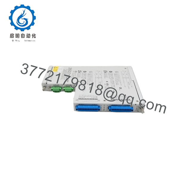
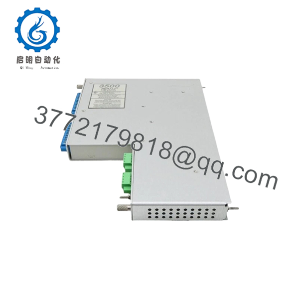
The Bently Nevada 135473-01 is a Keyphasor I/O Module for the 3500/25 Enhanced Keyphasor Module in the 3500 Machinery Protection System. It receives input signals from proximity probes or magnetic pickups and provides the physical interface required to generate precise shaft reference pulses for machinery monitoring.
Keyphasor signals establish the once-per-revolution (or multiple-per-revolution) timing reference used by vibration monitors to calculate shaft speed, phase angle, vector measurements, and synchronous vibration. Without a valid Keyphasor signal, many advanced diagnostic functions—including phase analysis and balancing—cannot operate correctly.
5. Installation & Configuration Guide
Stage 1 — Pre-Installation Preparation (10 Minutes)
⚠️ Safety First
- Notify operations before beginning maintenance.
- Shut down the protected machine if required by site procedures.
- Apply Lock-Out/Tag-Out (LOTO).
- Remove power from the 3500 rack.
- Wait at least 5 minutes before handling electronic assemblies.
Tools Required
- Grounded ESD wrist strap
- PH1 screwdriver
- Fluke 115 or equivalent multimeter
- Wire identification labels
- Smartphone for wiring documentation
- Laptop with 3500 Rack Configuration Software
Data Backup
- Export the rack configuration.
- Record Keyphasor channel assignments.
- Document probe types and cable routing.
- Photograph all rear terminal wiring.
- Record the installed firmware revision.
Stage 2 — Removing the Existing Module (5 Minutes)
- Remove the rear wiring cover.
- Label every probe cable before disconnecting.
- Disconnect all sensor wiring carefully.
- Remove the retaining hardware.
- Pull the I/O module straight out to avoid damaging the backplane connector.
Inspect for:
- Bent connector pins
- Damaged terminal blocks
- Corrosion
- Dust accumulation
⚠️ Do not discard the original module until the replacement has passed functional testing.
Stage 3 — Installing the New Module (10 Minutes)
- Wear a grounded ESD wrist strap.
- Verify the replacement part number is 135473-01.
- Confirm the installed front module is a compatible 3500/25 Enhanced Keyphasor Module.
- Install the rear I/O module evenly.
- Tighten the retaining hardware.
- Restore all field wiring according to the recorded documentation.
Self-Checklist
- ☑ Part number verified
- ☑ Correct I/O version installed
- ☑ Wiring restored
- ☑ Connector fully seated
- ☑ Retaining hardware tightened
Stage 4 — Power-On & Functional Testing (15 Minutes)
Pre-Power Checks
- Verify rack supply voltage.
- Inspect all Keyphasor wiring.
- Confirm proper connector engagement.
Startup Procedure
- Energize the 3500 rack.
- Verify normal LED startup on the associated Keyphasor monitor.
- Connect using 3500 Rack Configuration Software.
- Confirm the module is recognized.
- Verify Keyphasor pulse detection.
- Check shaft speed and phase measurements.
- Confirm communication with dependent vibration monitors.
- Review the event log for diagnostic faults.
⚠️ Troubleshooting Notes
No Keyphasor Signal
- Probe gap outside specification
- Incorrect probe polarity
- Open sensor cable
- Incorrect I/O module
Intermittent Phase Measurements
- Loose sensor connector
- Electrical noise
- Damaged extension cable
- Incorrect sensor type
Monitor Reports Configuration Fault
- Front module and rear I/O mismatch
- Incorrect rack configuration
- Unsupported hardware revision
Engineer’s Installation Notes
The most common mistake during Keyphasor replacement is assuming every rear I/O module for the 3500/25 is identical. It isn’t. Bently Nevada offers multiple I/O configurations with different barrier and termination options. Installing the wrong rear assembly may allow the module to power up, but the wiring layout or signal conditioning may not match the original installation.
Another issue I encounter during commissioning is probe gap adjustment. A healthy Keyphasor module cannot compensate for an improperly adjusted proximity probe. Before replacing electronics, verify the probe bias voltage and mechanical gap. Many “module failures” ultimately trace back to a transducer installation issue rather than defective hardware. These checks typically eliminate the majority of unnecessary troubleshooting time.

- 135473-01
6. Frequently Asked Questions (FAQ)
Q1. What is the purpose of the 135473-01?
The 135473-01 is the rear Keyphasor I/O Module for the 3500/25 Enhanced Keyphasor Module. It interfaces proximity probes or magnetic pickups with the monitor, enabling accurate shaft speed, phase, and timing measurements.
Q2. What is a Keyphasor signal used for?
A Keyphasor signal provides a once-per-turn (or multiple-per-turn) reference pulse synchronized with shaft rotation. This reference allows the 3500 system to calculate rotational speed, phase angle, synchronous vibration, and vector information used in machinery diagnostics.
Q3. Can I replace only the rear I/O module?
Yes, but the replacement must have the exact same part number and match the installed 3500/25 Enhanced Keyphasor Module. Using a different I/O option may result in incompatible wiring or signal conditioning.
Q4. Is the 135473-01 still available?
The part remains available through industrial automation suppliers as new original, new surplus, or tested surplus inventory. Lead times vary depending on stock and sourcing channels.
Q5. Why should I verify the I/O version before ordering?
The 3500/25 supports several rear I/O configurations with different barrier and termination options. Ordering solely by the front module model can result in receiving an incompatible rear I/O assembly that does not match your wiring or hazardous-area requirements.
Q6. What quality inspections should a supplier perform before shipment?
A qualified supplier should complete:
- OEM part number and serial number verification
- Anti-counterfeit inspection
- Visual inspection for corrosion, scratches, and repair marks
- Functional testing with a compatible 3500/25 module
- Keyphasor signal simulation using proximity probe or magnetic pickup inputs
- Connector continuity verification
- Insulation resistance testing (>10 MΩ)
- 24-hour operational burn-in
- ESD-safe packaging with QC sign-off
Requesting a functional test report or Keyphasor signal verification before shipment helps reduce commissioning delays, particularly for critical rotating equipment protection systems.



