
 WhatsApp: +86 16626708626
 Email:
  Phone: +86 16626708626
Description
Key Technical Specifications
| Parameter | Value |
|---|---|
| Model Number | 149992-01 |
| Manufacturer | Bently Nevada, a Baker Hughes business |
| Product Series | 3500 Machinery Protection System |
| Associated System Module | 3500/33 16-Channel Relay Module |
| Product Type | Spare 16-channel standard relay output module |
| Relay Output Count | 16 relay outputs |
| Module Height | Full-height 3500 rack module |
| Rack Installation Area | Slots to the right of the Transient Data Interface (TDI) Module |
| Relay Logic | Individually programmable Alarm Drive Logic |
| Logic Input Sources | Alarm states, NOT OK conditions, and individual proportional values from 3500 monitor channels |
| Logic Functions | Configurable AND and OR voting logic through 3500 Rack Configuration Software |
| Intended Output Use | Alarm annunciation, shutdown permissives, trip circuits, interposing relays, PLC/DCS discrete inputs, and status indication |
| Associated Control Module Spare | 149986-01, 16-channel relay control module |
| Standard Output Module Spare | 149992-01 |
| Failsafe Output Module Alternative | 149992-02 |
| Low-Current Output Module Alternative | 149992-03 |
| Low-Current Failsafe Alternative | 149992-04 |
| System Dependency | Requires the associated 3500/33 relay control module and compatible 3500 rack configuration |
| Service Role | Provides physical relay outputs; it does not directly accept vibration, speed, temperature, or process-transducer signals |
The OEM 3500/33 datasheet identifies 149992-01 as the spare standard 16-channel relay output module. It works with the 3500/33 16-Channel Relay Module architecture, where each relay uses programmable Alarm Drive Logic configured through 3500 Rack Configuration Software.
Product Introduction
The Bently Nevada 149992-01 is the standard relay output module used in a 3500/33 16-Channel Relay Module assembly. It provides 16 configurable discrete relay outputs for machinery-protection alarm annunciation, permissive logic, external shutdown interfaces, PLC or DCS status inputs, and interposing control relays.
This is the standard output version, not the failsafe or low-current variant. Its relay actions are determined by the associated 3500/33 relay control module and the configured Alarm Drive Logic. Verify the complete 3500/33 assembly, installed output-module type, relay wiring, contact duty, and trip philosophy before replacing it in a live machinery-protection rack.
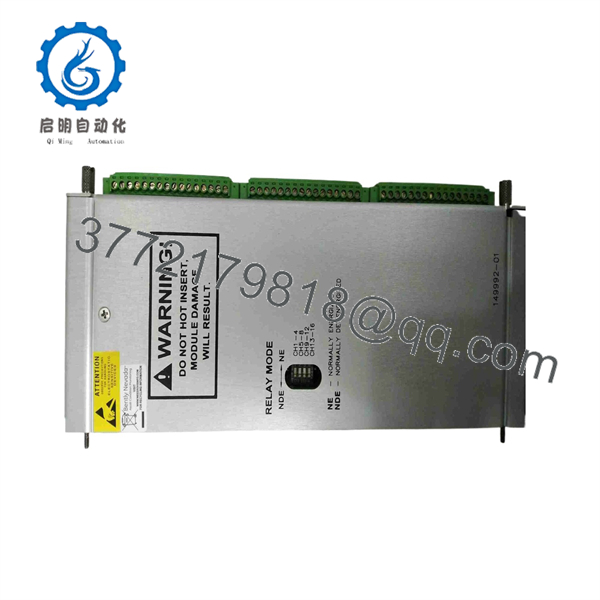
149992-01
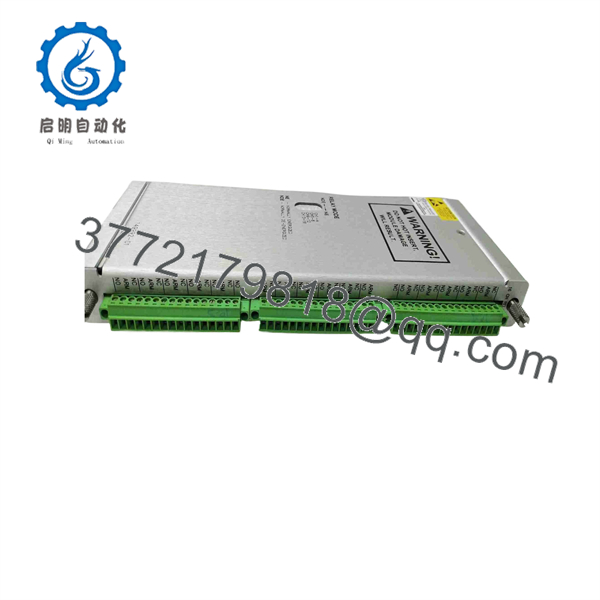
149992-01
Troubleshooting Quick Reference
| Symptom | Possible Cause | Relevance to This Part | Quick Check Method | Recommendation |
|---|---|---|---|---|
| One relay does not change state during a valid alarm | Incorrect Alarm Drive Logic, wrong monitor input selection, failed output relay, wiring fault, external load fault | ✅ High | Use 3500 Rack Configuration Software to identify the assigned logic inputs and relay state. Compare the module’s commanded relay state with continuity measured at the field terminals under an approved test procedure. | Verify logic and field wiring first. Replace the output module only if the relay fails to transition with a confirmed command. |
| Several outputs on the same module do not operate | Output module not seated, failed relay control module, rack backplane fault, lost configuration, common field supply issue | ✅ High | Check the 3500/33 control-module status, rack diagnostics, module seating, and shared external supply or common wiring. Compare with another known-good 3500/33 assembly if available. | Reseat under the approved procedure. Do not replace the 149992-01 until the control card, rack, and common field circuit are verified. |
| Relay contacts show correct state but external device does not energize | Open field fuse, failed interposing relay or solenoid, broken cable, incorrect external supply, load coil failure | ❌ Low | Measure the external control voltage at the load and the relay output terminal. Test the load circuit independently under site-approved isolation. | Diagnose the external circuit before replacing the relay output module. A dry contact cannot energize a load without the correct external supply. |
| Output remains energized after the alarm clears | Failsafe logic misunderstanding, latch/reset setting, programmed hold condition, welded relay contact, external backfeed | ✅ Medium | Review Alarm Drive Logic, latching/reset behavior, and the 3500 event log. With field wiring isolated, test contact continuity at the module terminal. | Correct configuration or external backfeed first. Replace the module if contacts remain closed with no commanded relay state. |
| Relay output is opposite of expected process state | NO/NC contact wired incorrectly, standard module installed where failsafe version was expected, logic inversion error | ✅ High | Compare the wiring drawing with actual terminal connections. Confirm that the installed spare is 149992-01, not 149992-02, 149992-03, or 149992-04. | Correct the wiring or output-module selection. Do not reverse wiring based on a live trial in a protection circuit. |
| New module causes unexpected trip or alarm | Incorrect relay configuration, output module type mismatch, field wires landed incorrectly, configuration changed, trip bypass removed too early | ✅ High | Apply the approved test/bypass procedure. Compare every terminal and relay assignment with the pre-removal photos and approved cause-and-effect chart. | Restore validated configuration and prove each output during a controlled functional test before returning equipment to service. |
| Relay chatters or output is intermittent | Loose terminal, unstable rack supply, vibration, relay contact wear, noisy logic input, external DC supply dropout | ✅ Medium | Trend the relay command in software and monitor external supply voltage. Inspect terminal torque, module seating, and the connected interposing relay. | Correct power and wiring issues first. Replace the 149992-01 if a verified relay command does not produce stable contact operation. |
| Entire 3500 rack shows faults | 3500/15 power supply failure, TDI issue, rack backplane fault, common configuration or communications problem | ❌ Low | Check rack power indicators, TDI status, other modules, and rack event logs. | Do not replace a single 149992-01 for a rack-wide fault. Diagnose rack-level power and communications first. |
| Burnt terminal or heat discoloration on one output | Loose terminal, overloaded contact, inductive load arcing, missing coil suppression, poor conductor torque | ✅ High | De-energize the circuit. Inspect conductor size, torque, load current, relay-contact condition, and suppression across DC coils or AC loads. | Replace damaged hardware and correct the load circuit. Install suitable suppression where approved; never raise fuse size to hide heating. |
❗ 149992-01 is the standard relay output version. It is not the failsafe, low-current, or low-current failsafe output module. The alternate spare numbers are 149992-02, 149992-03, and 149992-04. Installing the wrong version can reverse the expected trip behavior or exceed the intended load duty.
❗ Do not confuse output failure with bad relay logic. The 149992-01 only provides physical relay outputs. The associated 3500/33 control module and 3500 configuration determine why and when each relay changes state. Always confirm the commanded relay state in Rack Configuration Software before condemning hardware.
❗ Treat every field terminal as a live trip path until proven otherwise. These outputs may feed emergency shutdown circuits, turbine trip solenoids, compressor shutdown relays, annunciators, or DCS trip-status inputs. Follow the approved cause-and-effect, bypass, lockout, and functional-test procedure before moving wires.
❗ Take terminal photos before removal. This module has 16 output paths. A single wire landed on the wrong common, normally open, or normally closed contact can produce a false trip or a defeated protective function. Do not wire from memory.
If the problem remains unresolved, provide technical support with photos of the 149992-01 label, associated 3500/33 control-module label, rack position, output-terminal wiring, relay logic screenshots, event logs, external load voltage, and controlled continuity-test results. Keep these checks in mind and you will save yourself 90% of typical rework time.
Frequently Asked Questions (FAQ)
What is the Bently Nevada 149992-01 used for?
The 149992-01 is the standard spare 16-channel relay output module for a Bently Nevada 3500/33 16-Channel Relay Module. It supplies 16 configurable relay outputs driven by the 3500 machinery-protection system for alarm, shutdown, permissive, and external status functions.
Does the 149992-01 monitor vibration or accept sensor inputs?
No. It is a relay output module, not a vibration, temperature, speed, or proximity-monitoring card. Sensor inputs are handled by the appropriate 3500 monitor modules. The 3500/33 logic uses information already present in the rack to command the relay outputs.
What is Alarm Drive Logic?
Alarm Drive Logic is the configurable logic assigned to each relay. It can use alarm states, NOT OK conditions, or individual proportional values from one or more 3500 monitor channels. The logic can use AND and OR relationships and is configured with Bently Nevada 3500 Rack Configuration Software.
Is 149992-01 interchangeable with 149992-02?
No. The 149992-01 is the standard relay output module. The 149992-02 is the failsafe relay output version. Bently Nevada also lists 149992-03 as a low-current relay output module and 149992-04 as a low-current failsafe module. Match the installed output-module number and the protection-system cause-and-effect documentation exactly.
Can I hot-swap the 149992-01?
Do not assume hot swapping is permitted. Removing this module may change alarm, permissive, trip, or status circuits that affect operating equipment. Use the plant’s approved machinery-protection bypass, alarm-management, work-permit, and functional-test procedure before servicing a 3500/33 relay assembly.
Why does a relay show the correct logic state but fail to energize the external load?
Start outside the 3500 rack. Check the external control voltage, fuses, interposing relay or solenoid coil, load wiring, terminal torque, and return/common wiring. The 149992-01 provides relay contacts; it does not create the external supply voltage needed by the load.
Will replacing the output module erase the relay logic configuration?
The relay logic is configured through the 3500 system and associated 3500/33 control-module setup, rather than being solely stored in the output module. Still, record and back up the complete rack configuration before replacement. A wiring error, wrong output-module variant, or missed configuration change can create an immediate trip or alarm when the replacement is installed.
Is the 149992-01 obsolete, and should I keep a spare?
Treat it as a critical legacy machinery-protection spare. In racks where 3500/33 outputs feed turbine, compressor, generator, or pump shutdown logic, a spare should match the exact standard output version and be stored in ESD-safe packaging. Keep the latest Rack Configuration Software backup, cause-and-effect chart, terminal photos, and approved functional-test procedure with the spare.



