
 WhatsApp: +86 16626708626
 Email:
  Phone: +86 16626708626
Description
Key Technical Specifications
| Parameter | Specification |
| Part Number | 149992-02 |
| Manufacturer | Bently Nevada (Baker Hughes) |
| Associated Main Module | 3500/33 16-Channel Relay Control Module (149986-01) |
| Relay Count & Type | 16 Single-Pole Double-Throw (SPDT) Relays |
| Operating Mode | Failsafe (Relay coils are normally energized; de-energize to trip) |
| Max Switched Current | 5 A (Resistive load) |
| Max Switched Voltage | 125 Vdc / 250 Vac max |
| Max Switched Power | 70 W @ 24 Vdc (AC: 150 VA) |
| Rack Slot Position | Full-height rear slot directly behind 3500/33 control card |
| Dimensions (H × W × D) | 241 mm × 24.4 mm × 99.1 mm (9.50 in × 0.96 in × 3.90 in) |
| Weight | 0.40 kg (1.0 lb) |
| Operating Temperature | −30°C to +65°C (−22°F to +149°F) |
Product Introduction & Supply Chain Strategy
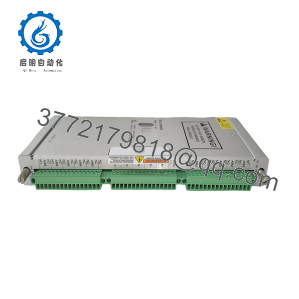
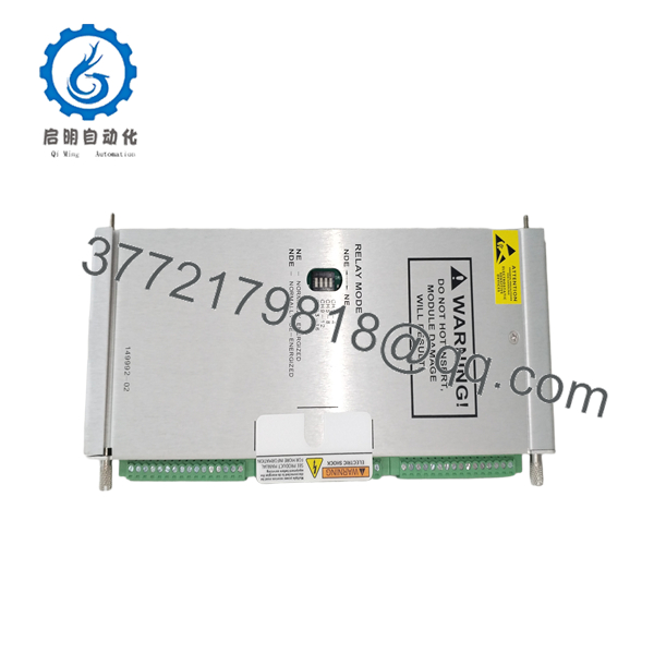
The Bently Nevada 149992-02 is a 16-channel failsafe relay output rear module used in tandem with the 3500/33 control card. Designed for critical machinery protection, this failsafe variant holds its output relays normally energized, ensuring that any loss of power, module failure, or rack disconnect instantly drops the relays into a safe “trip” state.
Securing this part as New Surplus guarantees uncompromised relay contact life and coil integrity, avoiding worn contacts and high-resistance pitting common in second-hand units. Keeping 1–2 New Surplus units in plant buffer stock safeguards against critical voting logic failures and eliminates costly trip system outages across your automated safety instrumented loops.

- 149992-02
- 149992-02
Installation & Configuration Guide
Stage 1: Pre-Installation (Prep & Safety)
- Bypass or disable downstream trip circuits at the Emergency Shutdown System (ESD) or Distributed Control System (DCS) interface to prevent accidental machine trips.
- Put on a grounded anti-static wrist strap attached directly to the 3500 rack ground frame.
- Mark and photograph field wiring connections on the terminal blocks prior to removal.
Stage 2: Removal
- Loosen the top and bottom captive thumbscrews on the existing rear 149992-02 card using a flathead screwdriver.
- Pull the module straight out along its card guide rails. Do not twist or rock the board to prevent bending the backplane pins.
Stage 3: Installation (Clone & Seat)
- Inspect the new 149992-02 backplane edge connector and relay contacts for zero physical defects.
- Align the board with the card guides in the rear full-height slot directly behind the corresponding 3500/33 control card.
- Slide the card in firmly until it seats into the backplane, then hand-tighten both top and bottom thumbscrews.
Stage 4: Power-On & Testing
- Reconnect field trip wiring to the internal terminal header blocks according to system schematics.
- Re-energize the 3500/33 slot; confirm the front 3500/33 control card displays a solid green “OK” LED and relays energize to their normal state.
- Remove system bypasses and verify relay channel status in the Bently Nevada 3500 System Configuration Software.
Firmware/Software Versions & Upgrade Notes
- Firmware Dependency: The 149992-02 is a hardware relay board containing no programmable flash firmware. All voting logic (AND/OR, Alert, Danger, Not-OK) is programmed into the front 3500/33 control card (149986-01).
- Software Configuration: Configured using Bently Nevada 3500 System Configuration Software.
- Failsafe Hardware Matching: Ensure the 3500 software configuration explicitly matches the “Failsafe” hardware selection. Selecting Non-Failsafe (149992-01) in software while using a 149992-02 physical module will invert relay logic and cause false trip conditions or failure to trip on fault.
Frequently Asked Questions (FAQ)
Is this unit a genuine New Surplus module or a refurbished part?
This product is a Brand New Surplus unit. It is not used, not pulled from a decommissioned plant, and not refurbished. All modules undergo rigorous quality verification to ensure OEM-level reliability.
What is the operational difference between Failsafe (149992-02) and Standard (149992-01) modules?
In the 149992-02 Failsafe module, relay coils are energized under normal operating conditions and de-energize to trip. This ensures that a complete loss of power to the 3500 rack automatically initiates a safe shutdown trip. In contrast, Standard (149992-01) modules are normally de-energized and energize to trip.
Why should I choose New Surplus over refurbished relay modules?
Electromechanical relays suffer mechanical wear, contact erosion, and coil degradation over time. Refurbished or used relay boards carry hidden contact pitting that can cause high resistance, intermittent trips, or failed contacts during an emergency event. New Surplus guarantees factory-rated contact resistance and 100% full operating lifecycle.
Can I hot-swap this rear relay module while the 3500 system is powered?
Yes, the 3500 rack supports hot-swapping under proper procedures. However, removing a failsafe relay card while downstream trip logic is active will immediately drop all 16 relays into their de-energized (trip) state. Always bypass external trip loops before pulling the card.
What warranty covers this 149992-02 module?
Every New Surplus 149992-02 module includes a full 1-year functional warranty. It ships tested and sealed in ESD-protective packaging complete with quality control sign-off documentation.



