
 WhatsApp: +86 16626708626
 Email:
  Phone: +86 16626708626
Description
Key Technical Specifications
| Parameter | Value |
| Channels | 2 isolated Keyphasor / Speed channels |
| Transducer Compatibility | Proximitor sensors, Magnetic pickups |
| Termination Style | Internal Terminations (Integrated screw terminal blocks) |
| Input Voltage Range | +1.0 V to −24.0 V Peak |
| Input Impedance | 20 kΩ minimum |
| Pulse Width Requirement | 2 μs minimum duration |
| Power Consumption | 2.5 W typical |
| Operating Temperature | −20 to +65 °C (−4 to +149 °F) |
| Operating Humidity | 95% non-condensing relative humidity |
Product Introduction & Supply Chain Strategy
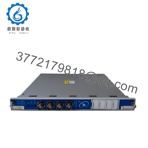
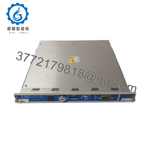
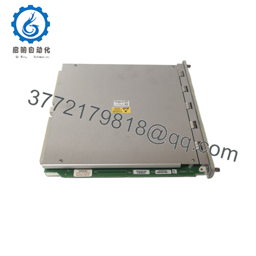
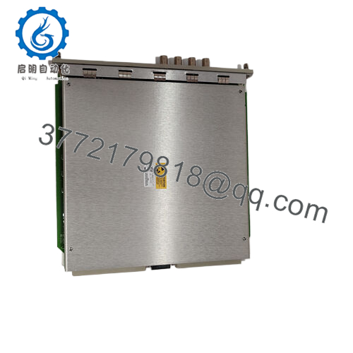
The Bently Nevada 1701/25-01 is a specialized dual-channel Keyphasor I/O card engineered specifically for the Trendmaster Pro architecture. The Trendmaster Pro system utilizes a distributed design to monitor large numbers of auxiliary and balance-of-plant assets across an entire facility. The 1701/25-01 accepts input signals from proximity probes or magnetic pickups, converting them into precise digital timing and phase reference points. These phase metrics are vital for calculating synchronized vector data, tracking exact rotational speeds, and executing filtered orbit analysis on rolling-element and fluid-film bearings.
From a procurement and inventory lifecycle standpoint, utilizing New Surplus 1701/25-01 modules is a crucial component of an optimized asset management strategy. Because the Trendmaster Pro line relies on localized processing nodes, an I/O card failure instantly blinds the system to critical phase information across multiple downstream assets. Securing factory-sealed surplus inventory provides the exact reliability and long service life of a direct OEM factory order while bypassing lengthy manufacturing lead times. This completely eliminates the Total Cost of Ownership (TCO) risks linked to refurbished cards, which often harbor latent thermal stress or degraded passive components that invite unexpected plant shutdowns.

- 1701/25-01
Installation & Configuration Guide
Stage 1: Pre-Installation (Prep & Safety)
- Verify that the localized enclosure housing the Trendmaster Pro chassis is isolated or clear for maintenance according to site safety protocols.
- Fasten a grounded, static-dissipative wrist strap to your arm and attach the alligator clip to a verified earth ground point on the metal chassis.
- Use the system configuration utility to pull a current configuration backup of the target node.
- Take a clear photograph of the existing field wiring entry points and note down any physical jumper allocations on the module housing.
Stage 2: Removal
- Loosen the upper and lower captive panel screws on the face of the 1701/25-01 I/O module using a flat-head screwdriver.
- Disengage the field terminal blocks from the card if they use a pluggable configuration, or systematically disconnect the wires if they are hardwired into the module block.
- Slide the card straight out of the slot channels, taking care not to scrape the circuit board components or trace pathways against adjacent hardware.
Stage 3: Installation (Clone & Seat)
- Remove the new surplus 1701/25-01 module from its sealed anti-static protective bag inside an ESD-protected zone.
- Double-check that any physical configuration jumpers on the new hardware board match the exact layout of the unit that was removed.
- Slide the card into the designated slot guides. Push the card home firmly until the backplane pins are completely seated in the master motherboard.
- Tighten the captive faceplate screws to secure the card to the frame and establish faceplate ground continuity.
Stage 4: Power-On & Testing
- Re-terminate the field signal and power wires to the internal screw terminal block, referencing your pre-installation notes.
- Energize the node power rail and watch the status LEDs on the module faceplate. The status light must cycle to a steady green indicator.
- Open the Trendmaster configuration interface to verify that the node recognizes the new 1701/25-01 hardware and that live speed/phase measurements are updating correctly in the system dashboard.
Firmware/Software Versions & Upgrade Notes
The 1701/25-01 interfaces with the broader Trendmaster Pro infrastructure via a shared backplane network. To ensure proper handshaking and avoid internal data dropouts, the system processor firmware must be compatible with the production revision of the I/O module.
A primary failure mode during card replacements is a firmware incompatibility error. If the replacement module contains a newer firmware build than the main processing block can read, the system will mark the card as “Not Communicating” or flag a hardware mismatch. Always verify the module’s revision level prior to insertion. Never attempt an ad-hoc firmware flash on a live system during production windows; any interruption to the power source during a flash sequence will damage the non-volatile memory chips on the module.
Frequently Asked Questions (FAQ)
What is the specific role of the 1701/25-01 within a Trendmaster Pro system?
The 1701/25-01 functions as the phase and speed reference input card. While standard Trendmaster cards collect general vibration data from accelerometers and velocity sensors, this module handles the pulse inputs from Keyphasor transducers. This tracking allows the system to calculate synchronous data, which is necessary for identifying specific machinery defects like imbalance, misalignment, or shaft cracks.
Is this 1701/25-01 module a used part that was cleaned up?
No. This component is classified strictly as New Surplus. It is an original OEM part that has remained un-deployed in an optimal, climate-controlled storage facility. It contains zero runtime hours, zero modification marks, and arrives in clean, factory-level condition. We do not source or offer used or refurbished equipment.
What is the difference between the 1701/25-01 and versions with other dashes?
The dash suffixes on Bently Nevada 1701 series components generally dictate internal termination styles, channel quantities, or specific safety certifications (such as ATEX / IECEx hazardous area options). The “-01” version features internal terminations, meaning the field cables terminate directly on screw blocks mounted to the module itself, eliminating the need for an external termination module.
Do I need to manually calibrate the Keyphasor inputs on this card?
No manual calibration is required. The 1701/25-01 reads incoming pulses based on voltage thresholds that you establish inside the Trendmaster configuration software. Once the trigger thresholds and sensor types are defined in software, the hardware automatically handles the input conditioning and timing metrics.
Will this card hold its configuration settings if power to the rack is completely lost?
The configuration parameters are stored in the non-volatile memory of the node controller and pushed to the I/O modules upon startup. If the rack loses power, the 1701/25-01 will not lose its configuration; it will automatically reload the correct operating parameters from the master controller as soon as power is restored to the backplane.


