
 WhatsApp: +86 16626708626
 Email:
  Phone: +86 16626708626
Description
Key Technical Specifications
| Parameter | Value |
|---|---|
| Model Number | 176449-08 |
| Manufacturer | Bently Nevada, a Baker Hughes business |
| Product Series | 3500 Machinery Protection System |
| Module Family | 3500/72M Recip Rod Position Monitor |
| Product Type | Four-channel reciprocating compressor rod position monitor |
| Input Type | Bently Nevada-compatible proximity-transducer inputs |
| Channel Count | Four independent measurement channels |
| Primary Measurements | Dynamic rod position and static rod position |
| Intended Machinery | Reciprocating compressors |
| Typical Use | Rod-drop monitoring, rider-band wear indication, rod-position monitoring, and compressor machinery protection |
| Input Impedance | 10 kΩ |
| Supported Sensitivity Options | 20, 100, or 200 mV/mil, depending on configuration and transducer system |
| Rod Position Scale Options | 0.79, 3.94, or 7.87 mV/µm, corresponding to 20, 100, or 200 mV/mil |
| Peak-to-Peak Filter Range | 1 Hz to 600 Hz |
| Gap Filter | −3 dB at 0.09 Hz |
| Typical Accuracy | ±0.33% of full scale |
| Maximum Accuracy | ±1% of full scale |
| Nominal Module Power | 7.7 W |
| Buffered Outputs | Four coaxial buffered transducer outputs |
| System Supply | 24 V DC rack supply |
| Alarm Functions | Configurable Alert and Danger setpoints; latching behavior configurable through software |
| Configuration Tool | Bently Nevada 3500 Rack Configuration Software |
| Associated I/O Module | 140471-01 I/O Module with internal terminations |
| Product Variant Note | 176449-08 identifies the 3500/72M monitor; it is not a standalone field transmitter or a complete sensor assembly |
The 176449-08 is listed as the Bently Nevada 3500/72M Recip Rod Position Monitor. It accepts four proximity-transducer inputs, provides static and dynamic position measurements, and supports user-programmable alarm setpoints for machinery protection of reciprocating compressors. The 3500/72M documentation lists 140471-01 as the I/O module with internal terminations for this monitor family.
Product Introduction
The Bently Nevada 176449-08 is a 3500/72M four-channel Recip Rod Position Monitor for machinery protection on reciprocating compressors. It accepts proximity-transducer signals, conditions them into dynamic and static rod-position measurements, compares values against configured alarm limits, and can drive system alarm or relay functions through the 3500 rack.
Plants use this monitor to identify rod-drop movement, rider-band wear, abnormal rod position, and developing compressor mechanical problems before they become a rod-load, packing, cylinder, or crank-end failure. The monitor requires a compatible 3500 rack, approved proximity-transducer system, correct 140471-01 rear I/O module, and a validated configuration for the actual compressor geometry.
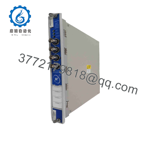
176449-08
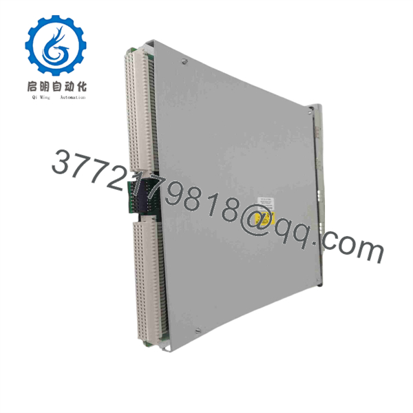
176449-08
Troubleshooting Quick Reference
| Symptom | Possible Cause | Relevance to This Part | Quick Check Method | Recommendation |
|---|---|---|---|---|
| One rod-position channel shows NOT OK | Failed proximity probe, damaged extension cable, open or shorted field wiring, incorrect gap voltage, loose I/O terminal | ✅ Medium | Use 3500 Rack Configuration Software to identify the affected channel. Measure probe bias/gap voltage at the 140471-01 I/O terminals and compare it with a known-good channel. | Check the probe, cable, connectors, and field wiring before replacing the 176449-08 front monitor. |
| All four channels show NOT OK | Monitor not seated, rear I/O module not seated, rack power fault, wrong configuration, backplane issue | ✅ High | Confirm the 176449-08 front monitor and 140471-01 rear I/O module are fully seated in the corresponding rack slot. Check rack PSU and TDI status. | Isolate power under the site procedure, reseat both cards once, and restore the validated configuration. Replace hardware only if the slot-specific fault persists. |
| Rod-drop value suddenly shifts | Probe bracket movement, loose mounting hardware, rod alignment issue, sensor gap change, cable damage, actual compressor mechanical event | ✅ High | Compare the current static position with baseline data. Inspect probe bracket hardware and measure gap voltage. Review compressor load, temperature, vibration, and maintenance history. | Treat a sudden shift as a possible machinery event first. Do not dismiss it as a monitor fault without checking the mechanical installation. |
| Reading is noisy or unstable | Poor shield termination, VFD or ignition-system noise, damaged cable, poor sensor ground, loose terminal, incorrect filter selection | ✅ Medium | Compare the buffered output waveform with a known-good channel using an approved oscilloscope method. Inspect shields, cable routing, terminal torque, and grounding. | Correct noise sources and wiring before changing the monitor. Do not use software filtering to conceal a bad sensor loop. |
| Alarm occurs immediately after replacement | Wrong channel configuration, wrong sensitivity setting, swapped sensor wires, incorrect baseline, alarm setpoints not restored | ✅ High | Compare the saved rack configuration with installed channel settings. Verify 20, 100, or 200 mV/mil sensitivity selection and confirm each probe channel assignment. | Reapply the validated configuration and perform a controlled functional check before placing the compressor back in normal operation. |
| Channel reads at a fixed maximum or minimum | Open circuit, short to common, failed Proximitor, incorrect probe system, damaged rear I/O terminal | ✅ Medium | Disconnect field wiring only under an approved protection bypass. Measure sensor supply and output at the I/O terminal, then compare with an adjacent healthy channel. | Trace the sensor loop and replace external components first. Replace the monitor only after confirming the field signal is valid. |
| Alarm remains active after rod position returns to normal | Latched alarm setting, reset not issued, setpoint logic configured for manual reset, relay logic state retained | ❌ Low | Review alarm-latch and reset settings in 3500 Rack Configuration Software. Check event logs and the panel or remote reset path. | Reset only after confirming the mechanical condition is safe. Do not change alarm behavior merely to clear a persistent alarm. |
| Buffered output is missing but measured value is valid | Damaged coaxial test connection, incorrect test setup, output cable fault, front-panel connector issue | ✅ Medium | Verify the internal measured value first, then test the buffered output using a known-good coaxial lead and approved high-impedance instrument. | If the internal reading remains correct and the buffered output is absent with verified test equipment, investigate the front monitor. |
| Entire 3500 rack has a communications fault | TDI issue, rack power problem, backplane failure, gateway/network fault | ❌ Low | Check TDI status, rack PSU indicators, other monitor cards, and system event logs. | The 176449-08 is a monitoring card, not a rack communications module. Diagnose rack-level faults before replacing it. |
| Module or terminals show corrosion or heat damage | Cabinet moisture ingress, loose terminal, field transient, poor sealing, contaminated compressor enclosure | ✅ High | De-energize the rack, inspect the module, rear I/O terminals, connector pins, and cabinet seals. Look for discoloration, corrosion, and loose conductors. | Replace damaged hardware and correct the ingress, wiring, grounding, or transient source before installing a replacement. |
❗ Do not call a rod-position alarm a bad card until you inspect the compressor. A genuine rod-drop or position shift can indicate rider-band wear, rod misalignment, loosened probe mounting, or a mechanical event. Compare current values with baseline data and inspect the physical sensor arrangement before resetting alarms.
❗ Record the existing configuration before removal. The 3500/72M can be configured for different transducer sensitivities and alarm values. Photograph the monitor and rear I/O labels, save the 3500 Rack Configuration Software file, record channel assignments, and note baseline rod-position values before swapping the 176449-08.
❗ Use the correct I/O module. The associated 3500/72M documentation lists the 140471-01 rear I/O module with internal terminations. Do not assume another 3500-series rear card uses the same field termination layout.
❗ Do not bypass a rod-position trip casually. This monitor may contribute to compressor protection logic. Any bypass, inhibit, simulated signal, or functional test must follow the site’s machinery-protection procedure, lockout requirements, and operational authorization.
If the diagnosis remains unclear, provide technical support with the 176449-08 label, 140471-01 rear I/O label, rack slot, saved configuration file, channel diagnostics, gap-voltage readings, buffered waveform captures, baseline rod-position trend, and recent compressor event log. Keep these checks in mind and you will save yourself 90% of typical rework time.
Frequently Asked Questions (FAQ)
What is the Bently Nevada 176449-08 used for?
The 176449-08 is a Bently Nevada 3500/72M Recip Rod Position Monitor used to monitor four proximity-transducer channels on reciprocating compressors. It provides dynamic and static rod-position measurements and compares them with configured Alert and Danger setpoints for machinery protection.
Does this module measure vibration?
It can process the dynamic component of a proximity-transducer signal, but its primary application is reciprocating compressor rod-position monitoring rather than general rotating-machine vibration monitoring. It is used for rod-drop movement, rider-band wear indication, and abnormal piston-rod position. For conventional shaft vibration applications, use the correct 3500 vibration monitor family rather than substituting a 3500/72M.
How many channels does the 176449-08 support?
It supports four independent proximity-transducer input channels. Each channel can be configured for the intended rod-position measurement and alarm application. Confirm the actual compressor sensor arrangement and the approved 3500 configuration before assigning or moving channels.
Which rear I/O module does it require?
The available 3500/72M product documentation lists 140471-01 as the I/O module with internal terminations for the 176449-08 monitor family. Match the installed rear I/O hardware and field termination arrangement exactly; do not select a rear module based only on physical appearance.
Can I hot-swap the 176449-08?
Do not assume it is hot-swappable. Removing the monitor can create NOT OK indications, loss of rod-position data, alarm changes, and potential impact on compressor protection logic. Use the approved protection bypass, alarm-management, work-permit, and controlled-return-to-service procedure before removal.
Why is one channel noisy while the other channels are stable?
The usual causes are local to that channel: damaged extension cable, poor shield connection, incorrect probe gap, loose terminal, a noisy Proximitor supply, sensor mounting movement, or electrical noise from nearby ignition, VFD, or power cabling. Compare its gap voltage and buffered waveform to a healthy channel before replacing the monitor.
Will changing the 176449-08 erase the compressor configuration?
The monitoring configuration is maintained in the 3500 rack configuration, but replacement work can still create incorrect readings if the software file, sensitivity selection, channel assignments, baseline values, or field wiring are not restored. Back up the configuration and document the installed wiring before the replacement.
Is the 176449-08 obsolete, and should I keep a spare?
Treat it as a specialized legacy machinery-protection spare. A failed monitor can remove rod-position visibility on a critical reciprocating compressor, and replacement availability may vary. Keep an identified spare with the correct 140471-01 I/O arrangement, current 3500 configuration backup, baseline data, wiring photos, and a controlled functional-test procedure.



