
 WhatsApp: +86 16626708626
 Email:
  Phone: +86 16626708626
Description
Key Technical Specifications
| Parameter | Value |
| Sensitivity | 3.94 mV/mm/s (100 mV/in/s) ±5% at 100 Hz |
| Frequency Response | 3.0 Hz to 900 Hz ±1.0 dB (1.5 Hz to 1.0 kHz ±3.0 dB) |
| Mounting Hardware Option (-04) | Stud M6x1 with 3/8-in 24 UNF adapter |
| Connection Option (-00) | Top-mounted MIL-C-5015 2-pin connector interface |
| Agency Approval Option (-00) | No hazardous area approvals |
| Velocity Range | 63.5 mm/s peak (2.5 in/s peak) |
| Case Material | 316L stainless steel |
| Operating Temperature | −40 to +85 °C (−40 to +185 °F) |
| Mounting Torque | 4.5 N·m ± 0.6 N·m (40 in·lbf ± 5 in·lbf) |
Product Introduction & Supply Chain Strategy
The Bently Nevada 190501-04-00-00 is a heavy-duty Velomitor CT (Cooling Tower) velocity transducer designed specifically to track casing vibration on low-speed machinery. It excels on cooling tower fans and air-cooled heat exchangers operating at or above 90 rpm. Standard velocity sensors lack the precision needed for these low rotational speeds, but the specialized piezoelectric core inside the 190501-04-00-00 captures sub-synchronous faults, motor unbalance, and gear reducer degradation before they cause structural failure.
From an inventory perspective, keeping this specific model as a New Surplus spare makes strategic supply chain sense. Cooling towers are highly corrosive, high-humidity environments that cause accelerated mechanical wear on field sensors. Procuring factory-sealed surplus stock minimizes your Total Cost of Ownership (TCO) compared to expensive direct factory orders, while protecting you from long lead times. Maintaining 1 or 2 new units on-site prevents un-monitored fan operation and eliminates the risk of using refurbished items, which often suffer from compromised hermetic seals or internal crystal aging that lead to inaccurate vibration readings.

- 190501-04-00-00
Installation & Configuration Guide
Stage 1: Pre-Installation (Prep & Safety)
- Lock-out and tag-out (LOTO) the power supply to the cooling tower fan motor to prevent accidental rotation.
- Ensure you are wearing an ESD wrist strap linked to a verified ground point when handling interconnecting cables.
- Clean the mounting surface thoroughly; it must be flat, smooth, and free of rust or debris to ensure proper frequency transmission.
Stage 2: Removal
- Unthread the MIL-C-5015 2-pin cable connector assembly from the top of the failed transducer.
- Use a wrench on the integrated hex base of the transducer to unseat it from the machine casing. Do not apply force to the top connector housing.
- Remove the old mounting stud assembly and inspect the casing thread integrity.
Stage 3: Installation (Clone & Seat)
- Unpack the new surplus 190501-04-00-00 sensor. Verify that the internal threads match the supplied M6x1 to 3/8-24 adapter stud.
- Apply a thin, uniform layer of silicone oil or mounting grease to the mounting interface to improve high-frequency coupling.
- Thread the stud into the base of the transducer, then screw the assembly into the machine casing.
- Use a calibrated torque wrench on the hex flats to tighten the sensor to 4.5 N·m (40 in·lbf). Over-torquing can fracture the internal crystals, while under-torquing reduces frequency response.
Stage 4: Power-On & Testing
- Align and thread the 2-pin MIL-C-5015 connector cable onto the top plug. Hand-tighten until firmly seated to protect the pins from moisture intrusion.
- Restore power to the monitoring rack (such as a Bently Nevada 3500 system).
- Check the bias voltage on the monitor channel; it should settle within the standard operational range (typically -10 Vdc to -13 Vdc).
- Verify that the system registers a healthy channel status light without a “NOT OK” or open-circuit fault.
Firmware/Software Versions & Upgrade Notes
The 190501-04-00-00 acts as a purely analog sensor, outputting an AC voltage signal proportional to vibration velocity. Because it has no digital firmware, it does not require firmware flashing or software upgrades.
However, you must verify the configuration parameters in your rack software (such as 3500 Configuration Software). Ensure the channel card configuration is set exactly to “Velomitor CT” rather than a standard “Velomitor” or generic accelerometer. Choosing the wrong sensor profile alters the filter thresholds and target frequency cut-offs, which can cause false alarms or prevent the system from picking up low-frequency faults under 10 Hz.
Frequently Asked Questions (FAQ)
What do the trailing numbers “-04-00-00” signify in this part number?
These numbers represent specific factory options chosen for the 190501 base model. The -04 option means the sensor includes an M6x1 to 3/8-in 24 UNF mounting adapter stud. The -00 connection option specifies a standard top-mount MIL-C-5015 2-pin electrical interface. The final -00 indicates that this unit does not carry hazardous area certifications (like ATEX or IECEx).
Can I use this sensor in an environment that requires explosion-proof ratings?
No, this specific configuration (ending in -00 for agency approvals) is meant for non-hazardous locations or standard industrial areas. If your cooling tower requires ATEX, IECEx, or CSA hazardous area approvals, you will need a configuration that includes options like -01 or -CN.
Why shouldn’t I just buy a cheaper refurbished or used 190501 sensor?
Refurbished vibration sensors carry a high hidden risk. Cooling towers expose sensors to continuous moisture, thermal cycling, and chemical treatments. Used sensors often have microscopic seal degradation that allows moisture to enter the internal electronics over time. This leads to signal drift, false trips, or complete sensor failure, making the cost of a single unplanned shutdown far higher than your initial savings.
How does this sensor differ from the standard Bently Nevada 330500 Velomitor?
The 190501 Velomitor CT is optimized for low frequencies. A standard 330500 Velomitor has a lower frequency limit of 4.5 Hz (270 cpm), making it blind to the low-speed rotations of cooling tower fans. The 190501 extends down to 1.5 Hz (90 cpm), allowing it to accurately capture the slower movement of fan blades and gearboxes.
Does this transducer require external power to operate?
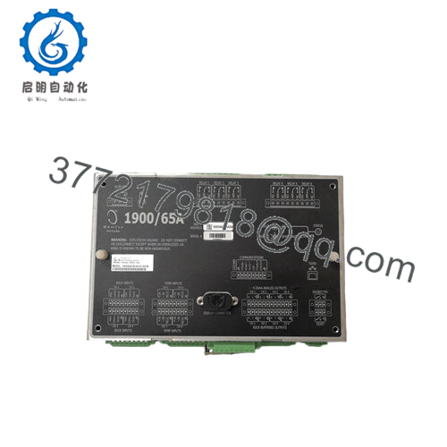
Yes. The 190501-04-00-00 requires constant current power, which is provided directly by the connected Bently Nevada monitor rack channel (e.g., 3500/42M or a 1900/65A monitor). It does not need an independent external power supply at the machine casing.


