
 WhatsApp: +86 16626708626
 Email:
  Phone: +86 16626708626
Description
Key Technical Specifications
| Parameter | Value |
| Tip Diameter | 5.0 mm (0.197 in) |
| Case Thread Metric (-02) | 3/8-24 UNF threads, unthreaded length option |
| Total Length (-12) | 1.2 meters (3.9 feet) |
| Connector Option (-05) | Miniature coaxial click-lock connector, gold-plated |
| Agency Approval (-02) | Multiple hazardous area approvals (ATEX, IECEx, CSA) |
| Linear Range | 0.25 mm to 1.25 mm (10 mils to 50 mils) typical |
| Scale Factor | 7.87 V/mm (200 mV/mil) when combined with 7200 Proximitor |
| Operating Temperature | −35 to +177 °C (−31 to +351 °F) |
| Tensile Strength | 330 N (75 lbf) probe-to-cable pull strength |
Product Introduction & Supply Chain Strategy
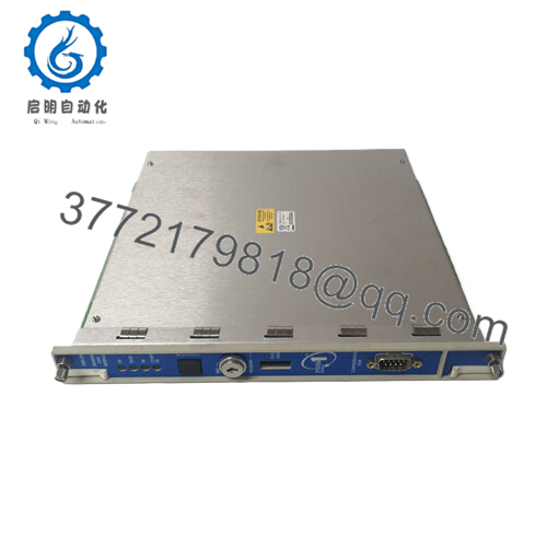
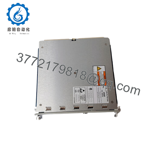
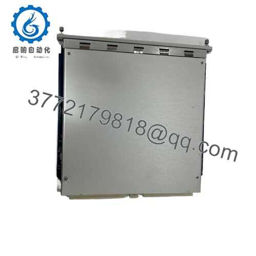
The Bently Nevada 21508-02-12-05-02 is a high-precision, 5mm eddy current proximity probe belonging to the legacy 7200 series machinery protection ecosystem. Mounted through bearing housings or internal brackets, this probe tracks micro-inch shaft movements on critical machinery like high-speed compressors, steam turbines, and industrial gearboxes. By establishing an electromagnetic field at its tip, the sensor monitors dynamic radial vibration, axial thrust position, and reference speed without making physical contact with the rotating target.
From a reliability and procurement standpoint, keeping this exact configuration as New Surplus is an essential risk-mitigation strategy. The 7200 series has been largely succeeded by newer platforms, making factory-ordered replacements subject to long lead times or high customization fees. Because proximity probes are installed in harsh environments exposed to hot lube oil, extreme thermal shifts, and mechanical stress, they face higher wear rates than rack electronics. Utilizing factory-sealed surplus stock avoids the high failure rates of refurbished alternatives, which often suffer from altered calibration curves or micro-fractures in the coaxial core that cause false alarms and expensive, unplanned production stops.

- 21508-02-12-05-02
Installation & Configuration Guide
Stage 1: Pre-Installation (Prep & Safety)
- Lock-out and tag-out (LOTO) the drive motor or power source for the machine train under service.
- Put on a grounded static-dissipative wrist strap before handling the probe’s miniature coaxial connectors to prevent electrostatic discharge damage to the downstream Proximitor sensor.
- Clean the mounting port threads thoroughly to remove residual lock-tite, metallic grit, or hardened sealant.
Stage 2: Removal
- Carefully unthread the miniature coaxial connector mating the probe cable to the extension cable. Protect the open connector ends with clean vinyl caps.
- Loosen the locknut on the old probe body using a deep-well socket or open-ended wrench.
- Unthread the probe body from the bracket or housing block, ensuring the cable rotates freely with the body to prevent wire twisting or internal kinking.
Stage 3: Installation (Clone & Seat)
- Unpack the new surplus 21508-02-12-05-02 probe and inspect the 5mm tip face for scratches or indentations.
- Thread the new probe into the mounting port by hand. Rotate the probe body and cable together as an assembly to keep the integrated armor jacket completely stress-free.
- Connect a digital multimeter to the corresponding Proximitor sensor output terminals to monitor the DC gap voltage during the mechanical adjustment phase.
- Advance the probe toward the shaft until the voltmeter reads the target electrical bias voltage—typically −10.0 Vdc, which corresponds to the exact center of the sensor’s linear calibration range. Tighten the locknut to 4.5 N·m (40 in·lbf) once the gap is verified.
Stage 4: Power-On & Testing
- Push the miniature coaxial connector into the extension cable lead until the physical click-lock engagement is felt. Wrap the connection point with self-fusing silicone tape to exclude oil and moisture.
- Power up the connected machinery monitor channel (such as a Bently Nevada 3500/42M).
- Confirm that the channel’s status display reads a healthy condition and that no “NOT OK” or circuit fault flags are tripped.
- Verify that the static gap reading matches your physical installation logs before clearing the machine for initial rotation.
Firmware/Software Versions & Upgrade Notes
As a purely analog, hardware-driven eddy current transducer, the 21508-02-12-05-02 does not possess microprocessors or flashing memory. It contains no digital firmware and requires no software parameter updates.
However, you must ensure that the associated proximity driver—the 7200 Proximitor sensor—is explicitly calibrated for a 5mm probe configuration using the correct system cable length. Mixing a 5mm probe with a 3300 series or 8mm Proximitor creates a major impedance mismatch, which shifts the scale factor away from the standard 200 mV/mil profile and causes highly inaccurate vibration metrics or false machinery shutdown commands.
Frequently Asked Questions (FAQ)
What do the numbers following the base model “-02-12-05-02” mean?
These sub-codes outline specific factory options for the 21508 base model. The first -02 specifies the case thread pattern and unthreaded length selection. The -12 defines the total probe and cable assembly length as 1.2 meters. The -05 selects the miniature coaxial connector style with a fluid-resistant armor sheath. The final -02 confirms that the unit includes multiple hazardous area agency certifications, such as ATEX and CSA approval ratings.
Why should we avoid refurbished proximity probes for turbomachinery?
Refurbished proximity probes are highly risky for critical machinery protection applications. Over years of deployment inside bearing housings, the probe’s internal copper coils, matching capacitors, and coaxial insulation degrade due to thermal cycling and exposure to hot oil. A refurbished probe may look clean on the outside but can suffer from insulation breakdowns or resistance drift, leading to signal instability, calibration errors, and false machine trips that can cost thousands of dollars in lost production.
Can this 7200-series probe be connected directly to a newer 3300 XL extension cable?
No, it is not recommended. The Bently Nevada 7200 series 5mm system uses specific electrical tuning parameters that differ from the 3300 XL family. Forcing a cross-generational cable connection changes the system’s electrical resonance, ruining the standard 200 mV/mil scale factor and causing major errors in your vibration data. Always match 7200 series probes with 7200 series cables and Proximitors.
Does this probe require a specific target material to read vibration correctly?
Yes. Like most standard Bently Nevada proximity probes, this unit is factory calibrated for AISI 4140 AISI steel targets. If your machine shaft is made of a different material alloy—such as 304 or 316 stainless steel, K-Monel, or Inconel—the sensor will output a distorted scale factor. For non-standard shaft metallurgy, you must apply a custom calibration curve within your monitor configuration software.
What is the purpose of the armor cable layer on this model?
The flexible stainless steel armor jacket provides robust mechanical protection for the internal coaxial cable. It prevents the cable from being crushed, cut, or kinked by moving parts, flying debris, or sharp metal edges inside the bearing housing or terminal junction box, ensuring consistent signal transmission in harsh industrial environments.


