
 WhatsApp: +86 16626708626
 Email:
  Phone: +86 16626708626
Description
3. Key Technical Specifications
| Parameter | Value |
| Channel Count | 2 Independent Channels (Dual Configuration) |
| Full-Scale Range Option (-01) | 0 to 25 mm (0 to 1.0 inch) |
| Recorder Output Option (-01) | 4 to 20 mA dc, galvanically isolated |
| Relay Output Option (-01) | Dual-relay configuration (Alert and Danger) |
| Safety Barrier Option (-00) | None (Standard configuration without internal zener barriers) |
| Transducer Compatibility | Linear Variable Differential Transformers (LVDT) |
| System Accuracy | Within ±1.0% of full scale range |
| Power Consumption | 4.5 watts maximum |
| Operating Temperature | 0 °C to +65 °C (+32 °F to +149 °F) standard backplane ambient |
4. Product Introduction & Supply Chain Strategy
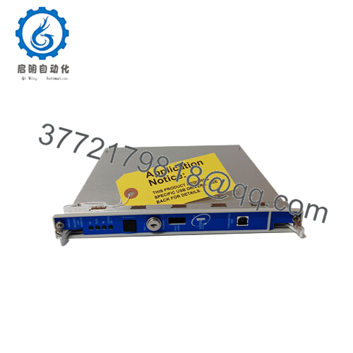
The Bently Nevada 3300/48-01-01-01-00 is a dual-channel Case Expansion Monitor designed for the legacy 3300 machinery protection rack. It tracks the structural displacement of a machine’s casing relative to its foundation, a metric critical during the startup and thermal ramp-up phases of large steam turbines and industrial gas compressors. By conditioning inputs from external Linear Variable Differential Transformers (LVDTs), this module prevents casing binding or shell distortion by providing real-time data and safety-interlock trip signals.
Because the Bently Nevada 3300 series is an obsolete system replaced by the modern 3500 platform, sourcing the 3300/48-01-01-01-00 as New Surplus is a highly critical supply chain strategy. Upgrading an entire rack to a newer monitoring generation can easily require capital expenditure exceeding $50,000 in hardware and unexpected engineering integration hours. Maintaining an on-site safety stock of New Surplus modules provides direct insurance against unexpected failures. This protects your operation from the dangerous calibration drift and degraded relays commonly found in used or unverified refurbished parts.
5. Installation & Configuration Guide
Stage 1: Pre-Installation (Prep & Safety)
- Put on a grounded ESD wrist strap before handling the replacement module. Static discharge can damage the sensitive input filters and analog-to-digital converters on the circuit board.
- Ensure the target monitoring channel is completely bypassed in the plant’s distributed control system (DCS) or emergency shutdown system (ESD) to prevent accidental trips.
- Document and photograph the rear terminal connections, paying close attention to the specific jumper configurations located on the circuit board itself.
Stage 2: Removal
- Unfasten the two thumb-screws located at the top and bottom of the 3300/48 front panel faceplate.
- Pull the module handles firmly outward to disengage the card’s multi-pin connector from the rack backplane.
- Slide the board smoothly along the metal chassis guide rails and place it directly into an static-shielding bag.
Stage 3: Installation (Clone & Seat)
- Set the programming jumpers on the new 3300/48-01-01-01-00 board to match the old module exactly (e.g., verifying bypass options, full-scale selection, and relay latching parameters).
- Align the module with the upper and lower slot guide rails in the 3300 chassis.
- Push the module backward firmly until it seats completely into the backplane, then lock it into position by hand-tightening the faceplate thumb-screws.
Stage 4: Power-On & Testing
- Reapply power to the monitor chassis. Observe the front panel LEDs during the initialization cycle.
- The green “OK” LED should turn on steady, and the numeric display should show a stable value corresponding to the baseline mechanical position of the LVDT transducer.
- Verify that the 4 to 20 mA loop sends an accurate baseline current back to your DCS or PLC terminal card.

- 3300/48-01-01-01-00
6. Firmware/Software Versions & Upgrade Notes
The Bently Nevada 3300/48 series operates purely on physical analog-digital circuitry and onboard hardware jumper settings rather than microchip-driven software firmware.
- Backplane Compatibility: This module requires a standard 3300 series system power supply and rack backplane to operate. It is not backward compatible with older 7200 systems, nor can it interface directly with modern 3500 networks without using a separate protocol converter or data communications gateway.
- Hardware Interlocks: Always verify that the relay logic setup on the motherboard (latching vs. non-latching, energized vs. de-energized) matches the original installation blueprint. Incorrect jumper placement will alter how the system behaves during an over-expansion event, which can lead to unsafe operation or a false plant trip.
7. Frequently Asked Questions (FAQ)
What do the individual options (-01-01-01-00) represent for this model?
The suffix breakdown specifies the physical configuration: the first -01 chooses a 0 to 25 mm full-scale range; the second -01 selects a 4 to 20 mA isolated recorder output; the third -01 enables a dual-relay configuration for alert and danger thresholds; and the final -00 dictates a standard option package without internal zener safety barriers.
Since the 3300 platform is obsolete, can I use a refurbished 3300/48 card?
Refurbished 3300 cards are pulled from old, decommissioned plants and have likely spent years under harsh environmental stress. The electromechanical safety relays on a refurbished module are prone to contact oxidation, and the analog electrolytic capacitors can dry out over time, causing serious measurement drift. Choosing New Surplus inventory is the only way to guarantee original factory reliability and keep your legacy protection system running safely.
Does this case expansion monitor work with standard eddy current vibration probes?
No. The 3300/48 is designed specifically to interface with Linear Variable Differential Transformers (LVDTs) or specialized long-stroke transducers that track slow, macro-scale thermal movement. Standard 8mm eddy-current proximity probes require different conditioning circuits, such as those found on a 3300/16 or 3300/20 vibration module.
How do I clear a latched alert or danger alarm condition on this module?
Alarms can be cleared by pressing the physical “RESET” button located on the front panel of the 3300 system rack interface module, or by bridging the external reset contacts provided on the rear terminal strip of the monitor backplane, provided that the actual thermal expansion has returned to a safe level below the programmed threshold.
Are the internal relays configuration-flexible via software programming?
No. All configuration logic for the 3300/48-01-01-01-00 is managed via physical circuit board jumpers located on the main printed wire assembly. You must manually place these jumpers into their correct positions before sliding the board into the rack chassis.



