
 WhatsApp: +86 16626708626
 Email:
  Phone: +86 16626708626
Description
Key Technical Specifications
| Parameter | Value |
|---|---|
| Manufacturer | Bently Nevada |
| Part Number | 330055-04-04-18-18-00-00-05-01 |
| Product Family | 3300 XL |
| Product Type | 8 mm Proximity Probe |
| Measurement Principle | Eddy-current proximity sensing |
| Probe Diameter | 8 mm |
| Probe Thread | 3/8-24 UNF |
| Probe Case Material | Stainless steel |
| Probe Length | 4.0 in |
| Extension Cable | 4 m |
| Extension Cable Type | Armored |
| Connector | Miniature coaxial connector |
| Target Application | Shaft displacement / position monitoring |
| Typical System | Bently Nevada 3300 XL Proximitor Sensor system |
| Installation | Threaded probe mounting |
| Intended Environment | Industrial rotating machinery |
| Configuration | Part-number-specific probe, extension cable, and connector arrangement |
Important: The complete 330055-04-04-18-18-00-00-05-01 ordering code defines a specific factory configuration. Do not substitute a visually similar 3300 XL probe solely because it has the same 8 mm diameter.
Product Introduction
The Bently Nevada 330055-04-04-18-18-00-00-05-01 is a configured 3300 XL 8 mm proximity probe assembly used for non-contact measurement of rotating-shaft position and displacement. It is intended for machinery protection and condition-monitoring systems where probe geometry, mounting thread, cable length, and electrical configuration must match the installed system.
The part number is important during replacement because the probe assembly is not defined only by its 8 mm sensing diameter. The mechanical probe configuration, extension cable, connector arrangement, and installation dimensions must be checked against the existing machinery-monitoring installation before procurement.
Installation & Configuration Guide
Stage 1: Pre-Installation Preparation — Approximately 10 Minutes
⚠️ Safety First: A proximity probe is normally installed around rotating machinery. Do not begin work until the machine is in the approved maintenance state and all applicable lockout/tagout procedures have been completed.
Tools Required
- ESD precautions where applicable
- Appropriate wrench for probe installation
- Multimeter
- Thread/installation measurement tools
- Wire labels
- Smartphone or camera
- Applicable Bently Nevada installation documentation
Before removing the existing probe:
- Record the complete installed probe part number.
- Photograph the probe, extension cable, connector, and routing.
- Record the existing probe-to-target gap if the maintenance procedure requires it.
- Identify the associated 3300 XL Proximitor Sensor.
- Record channel and rack position.
- Inspect the cable routing for damage or excessive bending.
- Confirm that the replacement part number is 330055-04-04-18-18-00-00-05-01.
Stage 2: Removing the Old Probe — Approximately 5 Minutes
- Place the machinery in the approved safe maintenance state.
- Isolate the applicable machinery and monitoring channel as required by site procedures.
- Photograph the existing installation.
- Mark the original cable routing.
- Disconnect the probe from the associated extension cable or monitoring circuit as applicable.
- Carefully remove the probe from its mounting location.
- Inspect the mounting threads and surrounding hardware.
- Check the old probe tip for mechanical damage or contamination.
⚠️ Do not rotate or pull the cable aggressively. The coaxial connection and probe cable can be damaged by excessive mechanical force.
Stage 3: Installing the New Probe — Approximately 10 Minutes
- Verify the replacement part number and physical configuration.
- Inspect the sensing tip for scratches, dents, contamination, or other damage.
- Check the 3/8-24 UNF mounting thread against the installed mounting arrangement.
- Route the cable along the original path.
- Avoid sharp bends, high-temperature surfaces, rotating components, and sources of excessive vibration.
- Install the probe into the mounting position.
- Do not use the cable or connector as a wrenching surface.
- Tighten the probe using the appropriate installation procedure and torque specification.
- Connect the extension cable and verify that the connector is fully seated.
- Confirm that the cable has adequate strain relief.
Probe Installation Self-Checklist
- Exact part number confirmed
- 8 mm probe configuration confirmed
- 3/8-24 UNF thread verified
- Probe tip undamaged
- Mounting position correct
- Cable routing reproduced
- Connector fully seated
- Cable protected from heat and moving machinery
- Probe gap set according to the applicable Bently Nevada procedure
Stage 4: Power-On & Testing — Approximately 10 Minutes
- Complete a final mechanical inspection.
- Restore the monitoring channel according to the site commissioning procedure.
- Confirm the associated Proximitor Sensor receives the expected probe signal.
- Check the monitoring system for channel faults.
- Verify the probe output at the monitoring interface.
- Compare the resulting shaft position/displacement reading with the expected baseline.
- Check for abnormal noise, unstable readings, or intermittent signal behavior.
- Verify the channel alarm and trip settings.
- Run the machine through the approved commissioning sequence.
- Record the final probe installation gap and operating reading in the maintenance record.
⚠️ Do not adjust alarm or trip limits merely to clear an unexpected reading. First determine whether the problem is mechanical installation, probe gap, cable routing, probe compatibility, or the associated Proximitor channel.
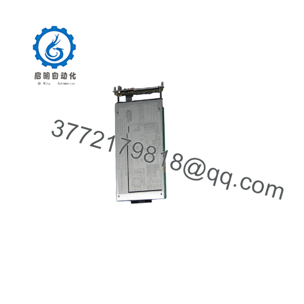
330055-04-04-18-18-00-00-05-01
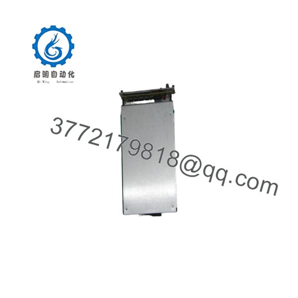
330055-04-04-18-18-00-00-05-01
Frequently Asked Questions (FAQ)
What is Bently Nevada 330055-04-04-18-18-00-00-05-01?
It is a specific Bently Nevada 3300 XL 8 mm proximity probe assembly configuration used for non-contact shaft displacement and position monitoring.
Is this probe compatible with every Bently Nevada 3300 system?
No. The 3300 XL designation and 8 mm diameter are not sufficient to establish compatibility. Verify the installed Proximitor Sensor, probe part number, extension cable arrangement, mechanical dimensions, and system documentation before ordering.
What does the long part number specify?
The complete ordering code identifies the factory configuration of the probe assembly. For procurement, use the complete 330055-04-04-18-18-00-00-05-01 number, not only “330055” or “3300 XL 8 mm.”
Can I replace it with another 8 mm proximity probe?
Not automatically. This is a common replacement mistake. Two 8 mm probes can have different thread arrangements, case dimensions, cable configurations, connector types, or electrical characteristics. Match the complete part number whenever possible.
Does the probe require a specific installation gap?
Yes. The probe-to-target gap is a critical parameter in an eddy-current displacement measurement system. Set the gap according to the applicable Bently Nevada installation procedure and verify the resulting electrical output before returning the channel to service.
Is 330055-04-04-18-18-00-00-05-01 new or refurbished?
The part number alone does not establish physical condition. For surplus inventory, request photographs of the actual unit and confirm whether it is Factory Sealed, New Original/New Surplus, or Refurbished/Tested. The warranty period should also be stated explicitly on the quotation.
What should I provide when requesting a replacement quote?
Provide the complete 330055-04-04-18-18-00-00-05-01 part number, photographs of the existing probe and connector, the associated Proximitor Sensor model, required quantity, required condition, and delivery deadline. For a critical machinery channel, also confirm whether an installed spare is available before removing the operating probe.



