
 WhatsApp: +86 16626708626
 Email:
  Phone: +86 16626708626
Description
Key Technical Specifications
| Parameter | Specification |
|---|---|
| Manufacturer | Bently Nevada |
| Model | 330101-00-08-05-02-05 |
| Product Family | 3300 XL 8 mm Proximity Transducer System |
| Probe Type | 8 mm eddy-current proximity probe |
| Measurement Principle | Non-contact eddy-current displacement |
| Thread Size | 3/8-24 UNF |
| Unthreaded Length | 0.0 in |
| Overall Case Length | 0.8 in |
| Integrated Cable Length | 0.5 m / 1.6 ft |
| Connector | Miniature coaxial ClickLoc |
| Cable Type | Standard cable |
| Connector Protector | None |
| Probe Configuration | Fully threaded case |
| Typical Application | Shaft vibration / axial position |
| System Compatibility | 3300 XL 8 mm Proximitor Sensor and compatible extension cable |
| Hazardous-Area Approvals | CSA, ATEX, IECEx |
| Mounting Hardware | Mounting clamp/bracket ordered separately where applicable |
| Calibration System | Must be used as part of a compatible probe/cable/Proximitor system |
The exact configuration is supported by the 3300 XL datasheet: 00 corresponds to 0.0 in unthreaded length, 08 to the 0.8 in case-length option, 05 to the 0.5 m cable, 02 to the miniature coaxial ClickLoc/standard-cable configuration, and the final 05 identifies the multiple-agency approval option.
Product Introduction
The Bently Nevada 330101-00-08-05-02-05 is an 8 mm 3300 XL eddy-current proximity probe for non-contact measurement of shaft displacement in rotating machinery. Its 3/8-24 UNF threaded body has a 0.8 in case length, with a 0.5 m integrated cable terminating in a miniature coaxial ClickLoc connector.
This configuration is intended for use with the compatible 3300 XL Proximitor Sensor and extension-cable system. The final suffix provides multiple agency approvals, including CSA, ATEX, and IECEx, making the exact configuration suitable for applications requiring the corresponding hazardous-area approvals.
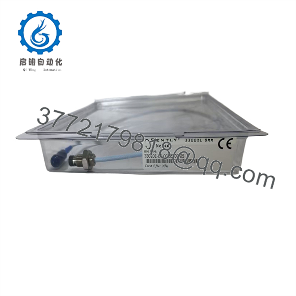
330101-00-08-05-02-05
Installation & Configuration Guide
Estimated replacement time: 30–60 minutes, excluding machinery shutdown, gap-setting verification, and vibration-system testing.
Stage 1 — Pre-Installation Preparation
- Confirm the existing probe is 330101-00-08-05-02-05 or verify the required replacement configuration from the equipment drawing.
- Confirm the existing system uses the 3300 XL 8 mm Proximitor Sensor family.
- Record the existing probe position, cable routing, connector identification, and installed gap.
- Prepare the required probe-setting tools, calibrated feeler/gapping tools, torque tools, labels, and ESD protection.
- Back up relevant machinery-monitoring configuration and record alarm/trip settings before maintenance.
- Apply the plant’s LOTO procedure and place the monitored machine in its approved maintenance state.
⚠️ The probe is part of a machinery-protection measurement chain. Do not change probe type, cable length, or Proximitor configuration without verifying the complete system.
Stage 2 — Removing the Old Probe
- Verify the machine is stopped and mechanically safe.
- Isolate electrical power where required by the machinery-maintenance procedure.
- Disconnect the probe’s ClickLoc connection from the extension cable.
- Protect the connector from oil, dirt, and mechanical impact.
- Loosen the probe mounting hardware.
- Remove the existing probe from its threaded mounting location.
- Record the removed probe’s part number and physical condition.
- Retain the old probe for configuration comparison.
⚠️ Do not pull the probe cable to disconnect the ClickLoc connector. Handle the connector body and protect the mating surfaces from contamination.
Stage 3 — Installing the New Probe
- Inspect the replacement probe for damaged threads, connector damage, or cable deformation.
- Verify the complete marking 330101-00-08-05-02-05.
- Confirm the mounting thread is 3/8-24 UNF.
- Install the probe into the existing mounting location using the approved mounting arrangement.
- Route the 0.5 m probe cable without sharp bends, excessive tension, or contact with moving/hot machinery.
- Connect the miniature coaxial ClickLoc connector to the compatible extension cable.
- Do not substitute an extension cable solely because the connector physically mates. The complete probe/cable/Proximitor system must maintain the specified electrical characteristics and calibration.
- Set the probe gap according to the applicable 3300 XL installation procedure and machinery-specific requirements.
The 3300 XL system is designed as a matched transducer system. Bently Nevada’s documentation should be used to confirm the required probe, extension-cable, and Proximitor combination before commissioning.
Stage 4 — Power-On & Testing
- Inspect the probe and cable routing before energizing the monitoring system.
- Restore power according to the plant procedure.
- Confirm the Proximitor Sensor produces a valid output.
- Verify the monitor reports a plausible shaft-position/gap signal.
- Check for intermittent signal, excessive noise, or unstable output.
- Confirm the installed probe gap is within the required operating range.
- Compare the vibration or position reading against the previous baseline where appropriate.
- Verify alarm and trip functions using the plant’s approved machinery-protection test procedure.
- Record the replacement part number, installation date, gap, and test results.
⚠️ Do not use a questionable probe signal to clear a machinery-protection alarm. Investigate the complete signal chain—probe, extension cable, Proximitor, monitor input, and configuration—before returning the machine to service.
FAQ
Q1. What is Bently Nevada 330101-00-08-05-02-05?
It is a 3300 XL 8 mm eddy-current proximity probe used for non-contact measurement of shaft displacement. The exact configuration has a 3/8-24 UNF thread, 0.8 in case length, 0.5 m cable, and miniature coaxial ClickLoc connector.
Q2. What does the 0.5 m cable specification mean?
The probe has 0.5 m / 1.6 ft of integrated probe cable. It is normally connected to an appropriate 3300 XL extension cable to achieve the required total electrical length for the Proximitor system. The extension cable should be selected according to the complete transducer-system configuration rather than physical length alone.
Q3. What thread does 330101-00-08-05-02-05 use?
This configuration uses a 3/8-24 UNF mounting thread. The 3300 XL documentation provides separate ordering options for 3/8-24 and M10 × 1 configurations, so the mounting thread must be checked before ordering.
Q4. Can this probe be connected directly to a PLC analog input?
Not as a generic analog sensor. The 330101-00-08-05-02-05 is part of the 3300 XL Proximity Transducer System and normally operates with the appropriate Proximitor Sensor and extension cable. The Proximitor provides the conditioned output used by the machinery-monitoring system.
Q5. Does 330101-00-08-05-02-05 have hazardous-area approvals?
The exact configuration is listed with CSA, ATEX, and IECEx multiple approvals. The actual installation must still comply with the applicable certificate, hazardous-area classification, wiring method, and system-level approval requirements.
Q6. Is the 330101-00-08-05-02-05 interchangeable with another 3300 XL 8 mm probe?
Not automatically. 3300 XL 8 mm probes differ in thread, case length, cable length, connector/cable configuration, and approval options. A replacement should match the original system configuration rather than simply matching the 8 mm probe diameter.
Q7. Is 330101-00-08-05-02-05 obsolete?
The exact part number appears in the 3300 XL datasheet’s list of commonly stocked probes, so it should not be treated as obsolete solely because it is an older 3300 XL part number. Current commercial availability and condition remain stock-dependent, and the actual unit should be verified as New Original, New Surplus, or Refurbished (tested) before purchase.



