
 WhatsApp: +86 16626708626
 Email:
  Phone: +86 16626708626
Description
Key Technical Specifications
| Parameter | Specification |
|---|---|
| Manufacturer | Bently Nevada |
| Part Number | 330130-080-00-05 |
| Product Family | 3300 XL 8 mm |
| Product Type | Standard Extension Cable |
| Cable Length | 8.0 m / 26.2 ft |
| Cable Construction | 75 Ω triaxial |
| Insulation | FEP |
| Typical Capacitance | 69.9 pF/m / 21.3 pF/ft |
| Cable Configuration | Standard, unarmored |
| Connector Type | ClickLoc coaxial |
| Agency Approval Option | CSA, ATEX, IECEx |
| System Scale Factor | 7.87 V/mm / 200 mV/mil |
| System Frequency Response | 0–10 kHz |
| Minimum Bend Radius | Approximately 25.4 mm / 1.0 in |
| Operating Temperature | -51 °C to +177 °C / -60 °F to +350 °F |
| System Application | Shaft vibration, axial position, speed/Keyphasor |
| Installation Position | Between probe and Proximitor sensor |
| Firmware | None |
| Programming | None |
The 8.0 m length and multiple-approval configuration are independently reflected in current product documentation and industrial inventory records. The cable is a passive component; its electrical characteristics matter because the probe, extension cable, and Proximitor form a matched measurement system.
Product Introduction
The Bently Nevada 330130-080-00-05 is an 8.0 m standard extension cable used in the 3300 XL 8 mm proximity transducer system. It provides the electrical connection between the proximity probe and the Proximitor sensor, allowing the signal-conditioning electronics to be installed away from the machinery measurement point.
The cable uses a 75 Ω triaxial FEP construction and is specified for high-temperature industrial machinery monitoring applications. The exact -05 configuration carries multiple agency approvals, including CSA, ATEX, and IECEx. Because cable electrical length is part of the transducer-system calibration, replacement should match the original system configuration rather than simply matching the physical cable length.
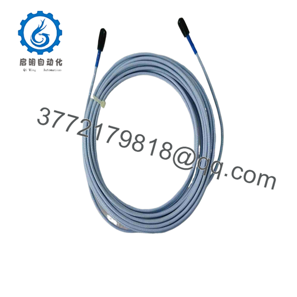
330130-080-00-05
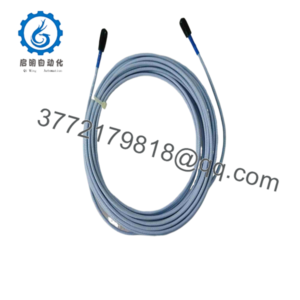
330130-080-00-05
Installation & Configuration Guide
Estimated replacement time: 20–45 minutes, excluding machine shutdown and signal verification.
Stage 1 — Pre-Installation Preparation
- Confirm the replacement part number is 330130-080-00-05.
- Verify that the existing measurement channel uses the 3300 XL 8 mm proximity transducer system.
- Record the existing probe part number, extension-cable length, Proximitor model, and cable routing.
- Photograph or label both cable connections before removal.
- Prepare ESD protection, labels, cable clamps, approved cleaning materials, and appropriate hand tools.
- Apply the plant’s LOTO procedure before working around the machinery and monitoring-system wiring.
- Verify that the replacement cable has the required hazardous-area approval for the installation.
⚠️ Do not replace an extension cable based only on connector appearance. The electrical length of the complete probe/cable/Proximitor combination must remain compatible.
Stage 2 — Removing the Old Cable
- Confirm the monitored machine is in a safe maintenance state.
- Disconnect the cable from the Proximitor sensor.
- Disconnect the opposite end from the probe lead.
- Handle the ClickLoc connectors by the connector body rather than pulling on the cable.
- Remove existing cable clamps or supports.
- Inspect the removed cable for abrasion, heat damage, oil ingress, or connector deterioration.
- Keep the old cable available for comparison with the replacement.
⚠️ Avoid contaminating or damaging the coaxial connector surfaces. A mechanically intact connector can still produce an intermittent vibration signal if the mating interface is contaminated or damaged.
Stage 3 — Installing the New Cable
- Compare the replacement against the removed cable.
- Confirm the cable is 8.0 m and marked 330130-080-00-05.
- Route the cable along the original path where practical.
- Maintain the manufacturer’s minimum bend radius; approximately 25.4 mm / 1.0 in is listed for this configuration.
- Keep the cable away from moving machinery, sharp edges, excessive heat, and sources of electrical interference.
- Secure the cable using suitable supports without crushing or sharply bending the cable.
- Connect one end to the compatible probe lead.
- Connect the other end to the compatible Proximitor sensor.
- Ensure both ClickLoc connections are fully seated.
- For hazardous-area installations, verify that the complete installation retains the required protection concept and certification.
Stage 4 — Power-On & Testing
- Inspect the entire cable route before energizing the monitoring system.
- Restore power according to the plant procedure.
- Confirm the Proximitor sensor produces a valid output.
- Check the corresponding monitor channel for a stable signal.
- Verify the probe gap and DC bias voltage according to the applicable 3300 XL procedure.
- Compare the vibration or axial-position reading against the previous baseline.
- Check for abnormal noise, signal dropouts, or unstable readings.
- Verify the machinery-protection alarm and trip circuits using the approved plant test procedure.
- Record the replacement part number and final test results.
⚠️ A new extension cable does not automatically correct an incorrect probe gap, defective Proximitor, damaged probe, or incorrect monitor configuration. Troubleshoot the entire measurement chain if the signal remains abnormal.
FAQ
Q1. What is Bently Nevada 330130-080-00-05?
It is an 8.0 m standard extension cable for the Bently Nevada 3300 XL 8 mm proximity transducer system. It connects the proximity probe to the Proximitor sensor.
Q2. What does the “080” in the part number mean?
The 080 designator corresponds to the 8.0 m / 26.2 ft cable-length option. This is a critical parameter because the total electrical length of the probe and extension cable is part of the calibrated transducer system.
Q3. What does “-00-05” mean?
For this configuration, -00 identifies the standard cable option, while -05 identifies the multiple-agency approval option. Current product documentation associates the -05 configuration with CSA, ATEX, and IECEx approvals.
Q4. Can I use a different-length extension cable as a replacement?
Not without checking the complete transducer-system configuration. The probe, extension cable, and Proximitor are designed as a matched electrical system. Changing cable length can change the system’s electrical characteristics and calibration. Match the original part number whenever possible.
Q5. Does 330130-080-00-05 require firmware or programming?
No. It is a passive extension cable and contains no processor or firmware. Configuration and signal conditioning are handled by the connected Proximitor and monitoring equipment.
Q6. What applications use this cable?
Typical 3300 XL applications include radial vibration, axial-position measurement, and Keyphasor/speed measurements on rotating machinery. The extension cable itself does not perform the measurement; it forms part of the signal path between the probe and Proximitor.
Q7. Is 330130-080-00-05 obsolete?
Some current distributors classify the exact part number as discontinued/obsolete by OEM, while other suppliers continue to list new or unused inventory. Therefore, lifecycle status and physical availability should be confirmed against the required delivery date.



