
 WhatsApp: +86 16626708626
 Email:
  Phone: +86 16626708626
Description
Key Technical Specifications
| Parameter | Value |
| System Length (-91) | 11.0 meters (36.1 feet) with patch cable and probe total |
| Mounting Option (-05) | Panel Mount (ruggedized zinc-plated aluminum housing) |
| Scale Factor | 7.87 V/mm (200 mV/mil) typical when paired with 8mm probe |
| Linear Range | 2.0 mm (80 mils) starting at roughly 0.25 mm (10 mils) from probe face |
| Supply Voltage Range | −17.5 Vdc to −26.0 Vdc at 12 mA maximum current consumption |
| Output Impedance | 50 Ω nominal |
| Frequency Response | 0 Hz (DC) to 10.0 kHz (+0, −3 dB limits) |
| Operating Temperature | −51 to +100 °C (−60 to +212 °F) |
| Agency Approvals | Multiple global hazardous area certifications (ATEX, IECEx, Class I Div 1) |
Product Introduction & Supply Chain Strategy
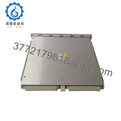
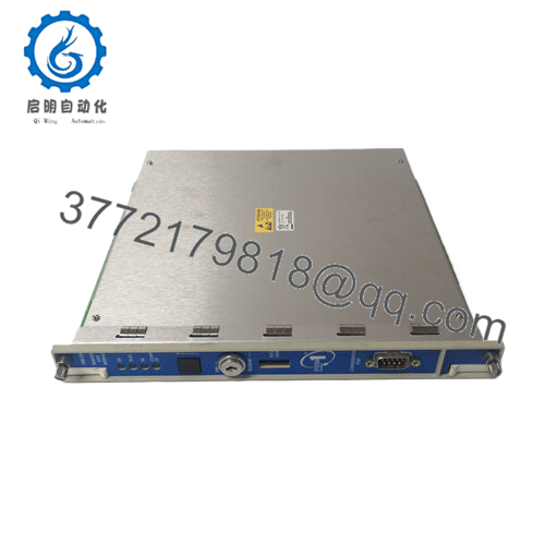
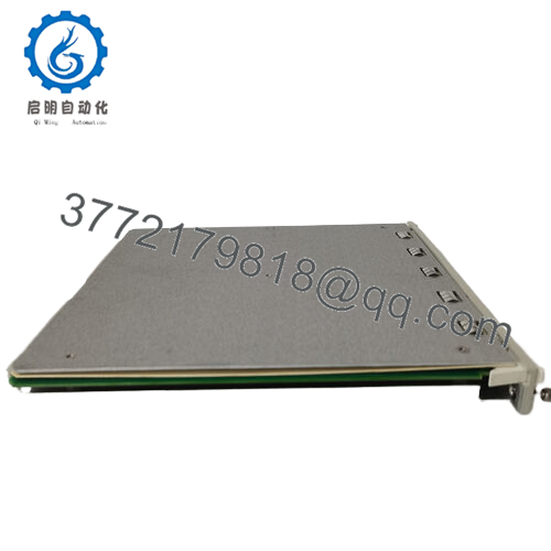
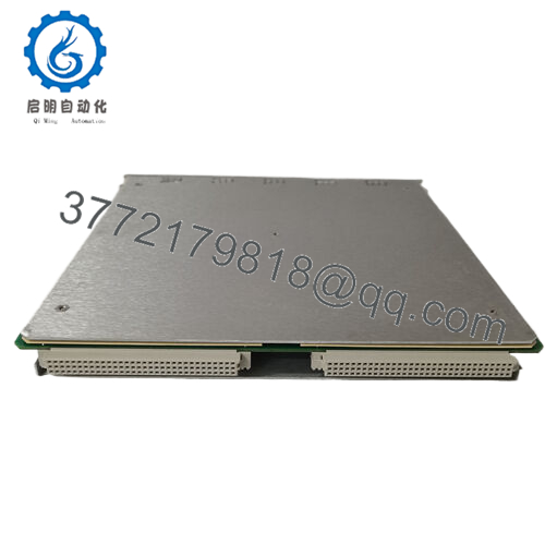
The Bently Nevada 330180-91-05 is the processing heart of the 3300 XL 8mm proximity transducer framework. Operating from a local enclosure or terminal housing, this active Proximitor sensor drives an RF signal down to an eddy current probe tip, creating a localized magnetic field. As the targeted machinery shaft moves relative to the probe face, the Proximitor demodulates the return signal, generating an output voltage directly proportional to the physical gap. This configuration is widely implemented on critical turbomachinery to track radial vibration, axial thrust position, and speed attributes.
From a reliability and procurement management perspective, stocking the 330180-91-05 as a New Surplus unit is an essential safeguard against high Total Cost of Ownership (TCO). Because the Proximitor relies on precise analog oscillator circuitry tuned to an exact 11-meter total length system, any component degradation causes immediate calibration drift. Sourcing factory-sealed surplus inventory bypasses lengthy manufacturer lead times and ensures the module matches OEM standards. This eliminates the operational risks associated with refurbished devices, where aged internal capacitors or corroded connection terminals can trigger false trip commands or, worse, blind the monitoring system during a critical machinery fault.

- 330180-91-05
- 330180-91-05
Installation & Configuration Guide
Stage 1: Pre-Installation (Prep & Safety)
- Place the target monitor channel in the Bently Nevada rack (e.g., 3500/42M) into Bypass mode to avoid an accidental machine trip.
- Confirm the host power rails are stable, and apply a grounded static-dissipative wrist strap linked directly to the cabinet ground.
- Clean the mounting plate location inside the local enclosure; verify that the existing extension cable length is marked as 11-meter system compatible.
Stage 2: Removal
- Disconnect the physical power/signal terminal block (VTX, COM, OUT lines) from the Proximitor base.
- Unthread the miniature coaxial connectors for both the probe input and the extension line. Use clean vinyl protective boots over the exposed coaxial ends.
- Loosen the four mounting screws anchoring the base of the failed unit to the panel rail, and lift the assembly clear.
Stage 3: Installation (Clone & Seat)
- Remove the new surplus 330180-91-05 from its original anti-static box within the ESD safe zone.
- Position the panel mount base over the existing chassis holes and secure the retaining screws to a tight, rigid fit.
- Attach the input coaxial cables. Push the miniature connectors firmly into place until the physical click-lock engagement is felt. Wrap the connection with self-fusing moisture-resistant silicone tape.
- Wire the terminal plug assembly back into the header block according to the standard scheme: Terminal 1 (VTX), Terminal 2 (COM), Terminal 3 (OUT).
Stage 4: Power-On & Testing
- Restore or confirm loop voltage (typically −24 Vdc).
- Using a high-impedance digital multimeter attached to the buffered output terminal lines, check the static DC gap voltage.
- Ensure the gap voltage aligns within the linear operating range (ideally centered around −10.0 Vdc with the machinery at rest).
- Verify that the monitoring rack reports a healthy loop indicator light, and remove the channel bypass setting once operational integrity is confirmed.
Firmware/Software Versions & Upgrade Notes
The 330180-91-05 Proximitor is a fully analog signal conditioner. It contains no digital microprocessors, flash chips, or embedded code layers; therefore, it requires no firmware modifications or software version synchronization.
However, you must confirm that the monitoring software configuration (such as the 3500 Configuration Software utility) lists the channel sensor type exactly as 3300 XL 8mm Proximitor. Selecting an older non-XL or an alternate probe diameter profile changes the expected input voltage boundaries, leading to incorrect vibration measurements or false system errors.
Frequently Asked Questions (FAQ)
What do the trailing numbers “-91-05” represent in this part number?
These digits dictate specific factory parameters for the 330180 base Proximitor line. The -91 option specifies that this driver is factory-calibrated for an 11-meter total system length (combining the physical probe length and the extension cable length). The -05 option dictates a Panel Mount physical footprint using a standard rectangular base plate, rather than a DIN rail clip mechanism.
Can I use this 11-meter Proximitor with a standard 5-meter extension cable assembly?
No. The internal oscillator and tuning circuitry inside the 330180-91-05 are configured specifically to match the electrical impedance of an 11-meter physical line. Connecting a 5-meter cable configuration alters the system resonance, which destroys the standard 200 mV/mil scale factor and causes severe measurement errors. You must match an 11-meter Proximitor with an 11-meter total probe and cable setup.
Is this unit a used or refurbished part that has been cleaned up?
No, this unit is strictly classified as New Surplus. It is original OEM inventory secured from un-deployed facility overstock. It has never been mounted in a field enclosure, has zero runtime hours, and arrives factory sealed. We maintain a zero-tolerance policy for used or refurbished parts.
What is the purpose of the coaxial click-lock connector on the Proximitor?
The miniature coaxial connector provides a secure, shielded interface for the incoming high-frequency RF signal from the extension cable. The integrated click-lock mechanism ensures a constant physical connection and prevents signal attenuation caused by machine case vibrations or cable movement.
Does this Proximitor include built-in hazardous area explosion-proof ratings?
Yes, the 330180 series comes standard with multiple agency approvals (such as CSA, ATEX, and IECEx certifications) for intrinsic safety when installed with approved barriers or enclosures. Always check the approval stamp on the module casing to verify it matches the hazardous area classification of your specific plant location.


