
 WhatsApp: +86 16626708626
 Email:
  Phone: +86 16626708626
Description
3. Key Technical Specifications
| Parameter | Specification Value |
| Full Part Number | 330191-00-60-90-05 |
| Probe Diameter | 8 mm |
| Unthreaded Length Option (-00) | 0.0 in |
| Overall Case Length Option (-60) | 6.0 in |
| Total Length Option (-90) | 9.0 meters (29.5 feet) with integrated cable |
| Agency Approval Option (-05) | Multiple Approvals (ATEX, IECEx, CSA Class I Div 1/2) |
| Thread Type | 3/8-24 UNF-2A thread configuration |
| Linear Range | 2.0 mm (80 mils) nominal range starting at 0.25 mm (10 mils) gap |
| Average Scale Factor (ASF) | 7.87 V/mm (200 mV/mil) when matched to 3300 XL Proximitor |
| Operating Temperature Range | −52 to +177°C (−62 to +351°F) for both probe tip and cable |
| Connector Type | Gold-plated coaxial ClickLoc miniature connectors |
| Tensile Strength | Patented CableLoc bond ensures up to 330 N (75 lbf) pull strength |
4. Product Introduction & Supply Chain Strategy
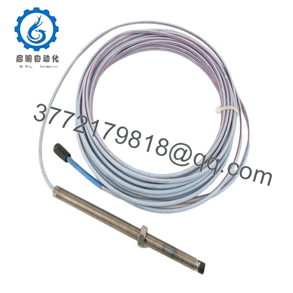
The Bently Nevada 330191-00-60-90-05 is a rugged, 8mm Extended Temperature Range (ETR) proximity probe designed to capture critical fluid-film bearing displacement metrics on high-speed rotating machinery. Engineered to withstand intense thermal environments up to +177°C, this system tracks precise micro-inch shaft variations—including radial vibration, axial thrust position, and tachometer Keyphasor timing signals—on heavy-duty industrial gas turbines, steam turbines, and large process compressors.
From a supply chain standpoint, matching exact probe options is a frequent bottleneck during unexpected plant turnarounds. Lead times for specialized ETR configurations from factory distribution channels regularly hit 8 to 10 weeks. Securing this part number as a verified Brand New Surplus unit avoids the severe material degradation risks of used or pulled sensors, which frequently suffer from brittle internal cables and cracked epoxy tips. Investing in 100% new components ensures absolute structural integrity and immediate parts availability, driving down your operational Total Cost of Ownership (TCO).

- 330191-00-60-90-05
5. Installation & Configuration Guide
Stage 1: Pre-Installation (Prep & Safety)
Ensure the monitoring rack channel controls are bypassed or powered down before installation to avoid accidental machinery trip sequences. Wear a grounded ESD wrist strap to protect the delicate internal transducer elements. Do not uncoil the 9.0-meter cable carelessly across concrete floors, which can cause micro-tears in the protective insulation. Take photos of the bracket position and measure the thread depth of the old probe before extraction.
Stage 2: Removal
Loosen the external locknuts on the old probe body assembly. Disconnect the gold-plated miniature ClickLoc coaxial connector from the extension cable or junction box terminal. Carefully back the probe housing out of the machine casing or bearing block, tracking the rotation to ensure the old lead cable does not bind, twist, or snap off during extraction.
Stage 3: Installation (Clone & Seat)
Thread the new 330191 probe into the mounting bracket or bore hole by hand until the tip approaches the target shaft face. Connect an electrical gap-meter or monitor the raw DC voltage output at the Proximitor sensor while turning the probe body. Set the installation gap to match your system spec—typically near −9.0 VDC (corresponding to a 50-mil physical gap gap-point). Once aligned, torque the main locknut to a maximum value of 4.5 N·m (40 in·lb) to prevent cracking the casing threads.
Stage 4: Power-On & Testing
Route the 9.0-meter integrated cable smoothly through the protective conduit tracks, maintaining a minimum bend radius of 25.4 mm (1.0 in). Finger-tighten the coaxial ClickLoc connector to the companion module until it clicks into place; do not use pliers. Re-apply power to the 3500 or 3300 monitoring rack, check that the channel bypass is cleared, and confirm that the monitor displays a steady, green “OK” status light without flagging a gap fault condition.
6. Firmware/Software Versions & Upgrade Notes
As a physical eddy-current sensor component, the 330191-00-60-90-05 probe does not run internal digital firmware code. However, its electrical performance requires strict system matched balance with your active monitoring rack hardware and software setup.
This 9.0-meter probe is specifically calibrated for direct execution alongside standard 3300 XL Proximitor Sensors. It cannot be mixed or spliced with legacy 3300 non-XL sensors or standard 5-meter electronics without severely shifting the scale factor away from the mandatory 200 mV/mil baseline. Always cross-check that your 3500 Rack Configuration software profile is set to “3300 XL 8mm ETR Probe” to ensure processing variables match the physical transducer’s unique thermal properties and prevent false alarm thresholds.
7. Frequently Asked Questions (FAQ)
What makes an “ETR” probe different from a standard Bently Nevada 8mm probe?
The ETR notation indicates an Extended Temperature Range configuration. While standard 3300 XL probes top out at a lower thermal threshold, the 330191 series uses specialized internal ceramic-matching matrix components and advanced insulation jackets. This allows both the probe body and its attached lead cable to function continuously in severe heat environments up to +177°C (+351°F) without drifting or causing signal attenuation.
Why is the total length option (-90) so critical during a hardware swap?
The total system electrical length must match the Proximitor sensor calibration perfectly. The “-90” option dictates a total probe length of 9.0 meters. Because this specific probe contains the entire 9-meter length within its own integrated cable, it connects directly into the Proximitor sensor without requiring an intermediary extension cable. Adding an extra extension cable to this module will unbalance the internal tuning, shifting the electrical scale factor and making the channel data completely inaccurate.
Is this a genuine original part, or has it been re-tipped or refurbished?
This unit is 100% Brand New Surplus inventory. We have a zero-tolerance policy for secondhand, pulled, or re-tipped proxy sensors. Re-tipped probes often exhibit compromised pressure seals and altered electrical impedance values, which can trigger unexpected signal failures inside critical turbomachinery loops. This item is an uninstalled, factory-sealed component complete with original gold plating intact.
What are the dangers of over-torquing the probe during thread mounting?
Over-torquing the 3/8-24 threads during installation can crush the inner structural barrel of the probe or fracture the internal TipLoc bond holding the ceramic tip to the stainless steel body. Always use a calibrated torque wrench and keep within the recommended installation parameter of 4.5 N·m (40 in·lb) maximum.
Can I run this probe cable through the same conduit as high-voltage motor power lines?
No. Proximity probes transmit low-voltage, high-frequency analog signals that are susceptible to cross-talk. To avoid corrupted vibration data or false machinery shutdowns, always route the 330191 cable through independent, grounded metal conduits away from AC motor power cables, VFD leads, and high-amp lines.
What kind of hazardous area safety approvals does the “-05” option provide?
The “-05” designator confirms Multiple Approvals certification. This ensures compliance with global safety frameworks, including ATEX/IECEx certifications for Zone 0/Zone 1 environments, alongside North American CSA approval markers for Class I, Division 1 and Division 2 hazardous industrial environments.



