
 WhatsApp: +86 16626708626
 Email:
  Phone: +86 16626708626
Description
Key Technical Specifications
| Parameter | Technical Specification |
| Model Code | 330191-02-10-10-00 |
| Total Length & Mounting (-02) | 5.0 meter (16.4 feet) system length, Panel Mount |
| Agency Approval (-10) | Multiple Approvals (CSA, ATEX, IECEx) |
| DIN Rail Option (-10) | Includes 35 mm DIN rail mounting clip |
| Country Option (-00) | Standard / No special country-specific certification |
| Power Input Range | −17.5 VDC to −26 VDC (Nominal −24 VDC) |
| Linear Range | 2.0 mm (80 mils), starting at 0.25 mm (10 mils) gap |
| Incremental Scale Factor (ISF) | 7.87 V/mm (200 mV/mil) \pm 5\% nominal |
| Target Material Calibration | AISI 4140 steel standard |
| Output Impedance | 50 \Omega nominal |
| Operating Temperature | −51°C to +100°C (−60°F to +212°F) |
| Dimensions & Weight | 81.3 mm x 61.2 mm x 43.2 mm (3.20 in x 2.41 in x 1.70 in) | 245 g (8.6 oz) |
Product Introduction & Supply Chain Strategy
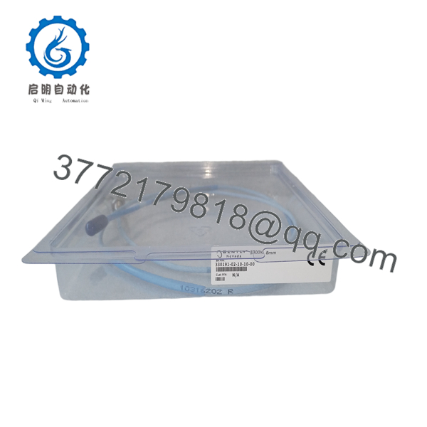
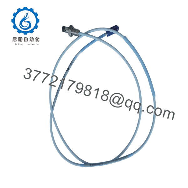
The Bently Nevada 330191-02-10-10-00 is a 3300 XL 8mm Proximitor Sensor configured for a 5.0-meter total system length. It generates an RF signal to power eddy-current proximity probes, conditioning the reflected field into a calibrated 200 mV/mil DC/AC output proportional to shaft position and dynamic vibration.
Maintaining this Proximitor as New Surplus protects critical turbomachinery from unexpected shutdown lockouts. Refurbished or aged proximity drivers often exhibit thermal drift, internal RF oscillator degradation, or noisy output signals, causing false machine trips or unrecorded shaft deflection. Stocking a verified New Surplus unit ensures exact scale factor accuracy, full API 670 compliance, and optimal Total Cost of Ownership (TCO).

- 330191-02-10-10-00
- 330191-02-10-10-00
Installation & Configuration Guide
Stage 1: Pre-Installation (Prep & Safety)
- Verify that the combined physical length of the connected probe lead (e.g., 0.5m) and extension cable (e.g., 4.5m) equals exactly 5.0 meters to match the -02 Proximitor calibration.
- Execute Lock-Out/Tag-Out (LOTO) on the cabinet power and trip interlock circuits.
- Put on a grounded anti-static wrist strap before handling internal wiring terminals.
Stage 2: Removal
- Unplug the terminal block connections for Power (V_{EE}), Signal (V_{OUT}), and Common (COM).
- Unscrew the triaxial extension cable connector from the Proximitor RF port.
- Unclip the housing from the 35 mm DIN rail or remove panel mounting screws.
Stage 3: Installation (Clone & Seat)
- Snap the new 330191-02-10-10-00 onto the 35 mm DIN rail or secure it to the panel enclosure.
- Hand-tighten the miniature triaxial extension cable connector onto the RF port until a distinct tactile click is felt.
- Reattach field wiring to the terminal strip: V_{EE} (−24 VDC), COM (Circuit Common), and V_{OUT} (Signal Output).
Stage 4: Power-On & Testing
- Measure incoming power to confirm supply voltage falls between −17.5 VDC and −26 VDC.
- Check the DC gap voltage at V_{OUT} using a digital multimeter; confirm it falls within the linear operational window (−9 VDC to −11 VDC for a 50-mil nominal gap).
- Confirm clean vibration spectrum readings on the 3500 or 2300 rack monitor before restoring automated trip protection.
Firmware/Software Versions & Upgrade Notes
The Bently Nevada 330191-02-10-10-00 Proximitor Sensor is an analog signal processing module and operates without microcode or programmable firmware.
- System Length Strictness: Always match 5.0m Proximitor drivers (-02) with 5.0m cable/probe combinations. Mismatches (e.g., using a 9.0m cable with a 5.0m driver) destroy the 200 mV/mil scale factor, introducing measurement errors over 30%.
- Target Material Tuning: Factory calibrated for AISI 4140 steel. If measuring non-standard shaft alloys (e.g., 304 Stainless Steel or Inconel), apply appropriate software scale factor correction factors in the monitoring system.
- Electrical Isolation: Ensure the aluminum baseplate remains electrically insulated or properly grounded per API 670 standards to avoid ground loop interference on the signal line.
Frequently Asked Questions (FAQ)
1. Is this Bently Nevada 330191-02-10-10-00 unit brand new or refurbished?
This product is a Brand New Surplus unit. It is not used, not pulled from a decommissioned plant, and not refurbished. All modules are stored in factory ESD packaging and undergo comprehensive quality checks prior to shipment.
2. What do the option numbers (-02-10-10-00) represent?
The breakdown translates as follows: 02 = 5.0 meter (16.4 ft) system length, Panel Mount; 10 = Multiple hazardous area agency approvals (CSA, ATEX, IECEx); 10 = 35 mm DIN rail mounting clip included; 00 = Standard country approval code.
3. Can I use this 5.0m Proximitor with a 9.0m total cable system?
No. Connecting a 9.0m cable/probe assembly to a 5.0m calibrated Proximitor driver (-02) shifts the RF resonant frequency, rendering the 200 mV/mil output inaccurate. You must use a 330191 module with the -01 option for 9.0m system lengths.
4. What is the purpose of the 35 mm DIN rail clip option (-10)?
The -10 option includes a factory-installed DIN rail mounting clip on the base plate, allowing immediate snap-in mounting on standard 35 mm DIN rails inside field junction boxes without purchasing extra adapters.
5. What warranty coverage comes with this New Surplus Proximitor Sensor?
Every New Surplus 330191-02-10-10-00 unit comes with a full 12-month replacement warranty. Units ship sealed in anti-static packaging with individual quality verification documentation.



