
 WhatsApp: +86 16626708626
 Email:
  Phone: +86 16626708626
Description
Key Technical Specifications
| Parameter | Value |
|---|---|
| Manufacturer | Bently Nevada |
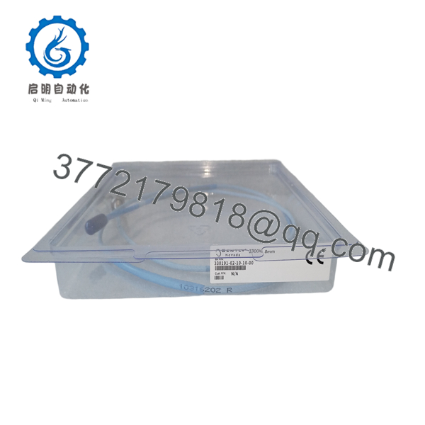
| Model Number | 330191-02-10-10-00 |
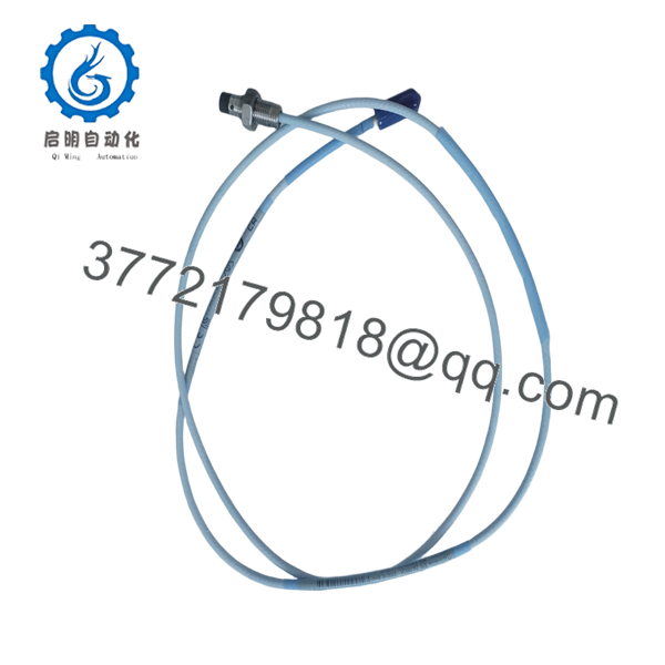
| Product Type | Reverse Mount Proximity Probe |
| Series | 3300 XL 8 mm Proximity Transducer System |
| Probe Mounting | Reverse Mount |
| Probe Thread | 3/8-24 UNF |
| Probe Cable Length | 2.0 m (6.6 ft) |
| Probe Tip Diameter | 8 mm |
| Agency Approval | Multiple Approvals |
| Compatible Extension Cable | 330130 Series |
| Compatible Proximitor® Sensor | 330180 Series |
| Primary Measurement | Shaft vibration, shaft position, and speed/keyphasor applications |
The 330191 probe is designed to operate only as part of a complete 3300 XL 8 mm Proximity Transducer System consisting of a probe, extension cable, and Proximitor® Sensor. The system is factory calibrated as a matched assembly.
Product Introduction
The Bently Nevada 330191-02-10-10-00 is a reverse-mount eddy-current proximity probe used for continuous monitoring of shaft vibration, axial position, and rotational speed on fluid-film bearing machines. It is commonly installed where access from the rear of the mounting bracket provides the most practical installation method.
Unlike a standalone sensor, this probe is one component of the calibrated 3300 XL 8 mm Proximity Transducer System. Probe length, extension cable length, and Proximitor® model must match the specified system configuration. Mixing components from different systems can introduce scale-factor errors and affect machinery protection performance.
Installation & Configuration Guide
Stage 1 – Pre-Installation Preparation (10 Minutes)
⚠️ Safety First
- Notify operations before shutting down the machine.
- Perform Lockout/Tagout (LOTO).
- Allow the rotor to come to a complete stop.
- Wear a grounded ESD wrist strap.
Required Tools
- Feeler gauge
- Dial indicator
- Digital multimeter
- Torque wrench
- Thread lubricant (if specified by OEM)
- Smartphone for documenting installation
Before removal:
- Record probe gap voltage.
- Photograph cable routing.
- Verify the complete part number.
Stage 2 – Remove Existing Probe (10 Minutes)
- Disconnect the extension cable.
- Remove cable clamps.
- Unscrew the probe carefully without twisting the cable.
- Inspect mounting threads for damage.
- Clean the mounting port before installing the replacement.
⚠️ Never rotate the probe by twisting the cable.
Stage 3 – Install the New Probe (15 Minutes)
- Confirm the replacement is 330191-02-10-10-00.
- Install the probe using the specified mounting torque.
- Route the cable away from high-voltage wiring.
- Connect the probe to the matching 330130 extension cable.
- Verify connector engagement.
Installation Checklist
- ✔ Correct probe model
- ✔ Correct cable routing
- ✔ Proper air gap established
- ✔ Cable protected from vibration
- ✔ Connectors fully tightened
Stage 4 – Commissioning & Functional Test (15 Minutes)
- Restore monitor power.
- Verify the probe OK voltage.
- Measure probe gap voltage.
- Confirm vibration readings remain stable.
- Compare readings with historical baseline values.
⚠️ Troubleshooting Tip
A fluctuating gap voltage after installation usually indicates improper probe spacing, loose connectors, or mechanical contact with rotating components. Verify the mechanical installation before replacing electronic components.

- 330191-02-10-10-00
- 330191-02-10-10-00
Frequently Asked Questions (FAQ)
Q1. Can this probe operate by itself?
No. The 330191-02-10-10-00 must be used with the matching 330130 extension cable and 330180 Proximitor® Sensor. The three components form a calibrated measurement system.
Q2. What does the ordering code mean?
- 330191 – Reverse Mount 3300 XL 8 mm Probe
- 02 – Reverse mount probe configuration
- 10 – 2.0 m probe cable
- 10 – Multiple agency approvals
- 00 – Standard connector/configuration (factory option)
Q3. Can I replace only the probe?
Yes, provided the replacement has the identical part number and remains compatible with the installed extension cable and Proximitor® Sensor. If cable damage or calibration concerns exist, replacing the complete transducer system is generally the better approach.
Q4. Where is this probe commonly installed?
Typical applications include:
- Steam turbines
- Gas turbines
- Centrifugal compressors
- Large pumps
- Electric motors
- Gearboxes
- Process compressors
- API 670 machinery protection systems
Q5. Why is probe cable length important?
The probe cable is part of the transducer system’s electrical calibration. Substituting a different cable length changes the system’s electrical characteristics and can affect measurement accuracy. Always install the exact model specified for the machine.
Q6. What installation mistake causes the most downtime?
The most common mistake is assuming any 3300 XL probe is interchangeable. The probe style, mounting method, cable length, extension cable, and Proximitor® Sensor must all match the original system specification. I’ve seen maintenance teams replace only the probe with a different cable-length version because the connector fit perfectly. The monitor remained operational, but shaft vibration readings shifted enough to trigger unnecessary machine trips. Always verify the complete ordering code before installation.



