
 WhatsApp: +86 16626708626
 Email:
  Phone: +86 16626708626
Description
Key Technical Specifications
| Parameter | Specification |
|---|---|
| Manufacturer | Bently Nevada |
| Model | 330500-02-00 |
| Sensor Type | Velomitor piezo-velocity sensor |
| Measurement | Absolute vibration velocity |
| Mounting Thread | M8 x 1 |
| Sensitivity | 3.94 mV/mm/s (100 mV/in/s) ±5% |
| Maximum Velocity | 1,270 mm/s (50 in/s) peak |
| Frequency Response | 4.5 Hz to 5 kHz |
| Transverse Sensitivity | Less than 5% |
| Amplitude Linearity | ±2% to 152 mm/s (6 in/s) peak |
| Mounted Resonant Frequency | Greater than 12 kHz |
| Dynamic Output Impedance | Less than 2,400 Ω |
| Output Bias | -12 ±3 VDC |
| Connector | 2-pin Mil-C-5015, hermetically sealed |
| Case Material | 316L stainless steel |
| Height | 63.2 mm (2.49 in) |
| Diameter | 25.3 mm (0.995 in) |
| Operating Temperature | -55 to +121 °C (-67 to +250 °F) |
| Weight | Approximately 0.142 kg |
| Agency Approval | None; -00 configuration |
The available technical listings consistently identify -02 as the M8 x 1 mounting configuration and -00 as the no-agency-approval option. Published specifications also identify the 330500 as an integrated piezoelectric velocity sensor rather than a conventional moving-coil velocity pickup.
Product Introduction
The Bently Nevada 330500-02-00 Velomitor Piezo-Velocity Sensor is an integrated piezoelectric sensor for measuring absolute vibration velocity on bearing housings, machine casings, and other structural surfaces. Its -02 configuration uses an M8 x 1 mounting thread, while the -00 suffix specifies no agency approval requirement.
The sensor uses embedded electronics and has no moving mechanical components. With a nominal sensitivity of 3.94 mV/mm/s and a velocity capability up to 1,270 mm/s peak, it is suited to vibration monitoring on rotating machinery such as pumps, fans, compressors, and other balance-of-plant equipment.
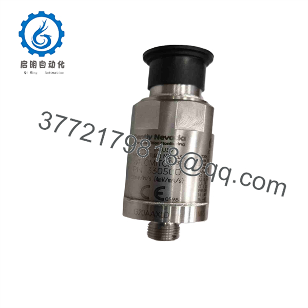
330500-02-00
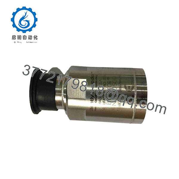
330500-02-00
Installation & Configuration Guide
Stage 1 — Pre-Installation Preparation
Estimated time: 15–20 minutes
- Confirm the replacement marking is exactly 330500-02-00.
- Verify that the existing mounting arrangement accepts an M8 x 1 thread.
- Confirm that the installation does not require hazardous-area agency approval. The -00 configuration has no agency approval.
- Apply LOTO to the associated monitoring circuit where required.
- Prepare an appropriate wrench, multimeter, wiring labels, installation documentation, and ESD protection.
- Record the existing cable polarity and terminal assignment before disconnecting the sensor.
- Photograph the existing installation and retain the old sensor for configuration and dimensional reference.
⚠️ Do not treat 330500-02-00 as an intrinsically safe or hazardous-area-approved substitute simply because another 330500 configuration carries an approval suffix.
Stage 2 — Removing the Existing Sensor
Estimated time: 10–15 minutes
- Verify the circuit is de-energized according to the plant procedure.
- Allow connected electronics to discharge before handling the wiring.
- Label the two conductors before removal.
- Disconnect the 2-pin Mil-C-5015 connector without pulling on the cable.
- Remove the existing sensor from the mounting surface.
- Inspect the mounting thread, mating surface, connector, and cable for mechanical damage or contamination.
⚠️ Do not rotate the sensor by twisting the connected cable or connector.
Stage 3 — Installing the 330500-02-00
Estimated time: 10–15 minutes
- Clean the mounting surface and verify that the M8 x 1 mounting thread is undamaged.
- Install the sensor squarely into the mounting point.
- Apply the manufacturer’s specified mounting torque. Published listings give a maximum torque of approximately 40 in-lb (46 kg·cm).
- Connect the 2-pin connector and confirm correct polarity.
- Route the cable away from high-current power conductors and sources of mechanical abrasion.
- Ensure the sensor body is firmly seated against the intended measurement surface.
Stage 4 — Power-On & Testing
Estimated time: 15–30 minutes
- Remove LOTO according to the approved plant procedure.
- Energize the monitoring circuit.
- Verify the sensor bias/output condition against the applicable Bently Nevada monitoring interface.
- Check that the vibration signal responds to normal machine conditions.
- Compare the measured vibration with historical baseline data where available.
- Confirm that no open-circuit, excessive-noise, or polarity fault is reported.
- Record the replacement date, sensor model, machine position, and test results.
⚠️ Do not commission the sensor based solely on physical fit. Verify the electrical interface, polarity, mounting thread, environmental requirements, and required approvals before returning the machinery to service.
FAQ
Q1. What is the main function of the 330500-02-00?
It measures absolute vibration velocity on a machine casing, bearing housing, or other structural mounting point. It is a Velomitor piezo-velocity sensor with integrated electronics.
Q2. What does the “-02” suffix mean?
For the 330500 series, -02 specifies the M8 x 1 mounting-thread configuration. The final -00 specifies the no-agency-approval configuration.
Q3. Can 330500-02-00 be installed in a hazardous area?
Not on the basis of this part number alone. The -00 configuration is listed as having no agency approval. If the installation requires CSA, ATEX, IECEx, or another hazardous-area certification, select the appropriate approved configuration and verify the complete installation against the applicable certification requirements.
Q4. Does this sensor require an external integrator?
The 330500 Velomitor incorporates electronics that provide a velocity-related output, so it is not simply a raw piezoelectric accelerometer requiring a separate external mechanical integrator. The receiving monitor or acquisition system must still be compatible with the sensor’s electrical output and bias characteristics.
Q5. Is 330500-02-00 a direct replacement for every 330500-series sensor?
No. The mounting thread, approval configuration, connector arrangement, and installation requirements must match. Other 330500 variants can use different mounting and approval options. Verify the complete part number before substitution.
Q6. Is the 330500-02-00 still available?
Availability varies by supplier and inventory condition. Current market listings show new, surplus, and other inventory categories, with lead times ranging from stock availability to several weeks. Confirm the actual condition—New Original, New Surplus, or Refurbished (tested)—before purchase.
Q7. What should be verified before ordering a replacement?
Verify the exact 330500-02-00 suffix, M8 x 1 mounting requirement, required approvals, connector/cable compatibility, machine mounting location, and receiving monitor input requirements. For safety-critical machinery, use the applicable Bently Nevada documentation and site engineering standard as the final authority.



