
 WhatsApp: +86 16626708626
 Email:
  Phone: +86 16626708626
Description
Key Technical Specifications
| Parameter | Specification |
|---|---|
| Manufacturer | Bently Nevada |
| Model | 3500/22M |
| Part Number | 138607-01 |
| Product Type | Standard Transient Data Interface Module |
| System | 3500 Machinery Protection System |
| Module Function | Transient data interface and rack data collection |
| Rack Position | Slot adjacent to power supplies |
| Host Communication | Ethernet through compatible TDI I/O module |
| Host Software | System 1 Condition Monitoring and Diagnostic Software |
| Configuration Software | 3500 System Configuration Software |
| Monitor Compatibility | 3500 M-series monitors, including 3500/40M and 3500/42M |
| Data Acquisition | Steady-state and transient dynamic data |
| Static Data Capture | Standard |
| Dynamic Data Capture | Available according to configured options |
| High-Resolution Transient Capture | Configuration-dependent |
| Standard Rear I/O | 146031-01, 10Base-T/100Base-TX copper Ethernet |
| Fiber I/O Option | 146032-01, 100Base-FX |
| Approx. Weight | 0.82 kg |
| Typical Application | Machinery condition monitoring and protection |
The OEM ordering information identifies 138607-01 as the standard 3500/22M TDI and lists 146031-01 as the corresponding 10Base-T/100Base-TX I/O module option. The TDI is installed in the rack slot adjacent to the power supplies.
The 3500/22M combines the rack-interface functions associated with the 3500/20 RIM with data-collection functions for steady-state and transient information. Dynamic/high-resolution transient acquisition depends on the applicable configuration rather than being implied solely by the 138607-01 part number.
Product Introduction
The Bently Nevada 3500/22M 138607-01 is the Standard Transient Data Interface module for the 3500 Machinery Protection System. It provides the interface between the 3500 rack and compatible Bently Nevada software, including System 1 and 3500 System Configuration Software, while collecting steady-state and transient data from M-series monitoring modules.
The module occupies the dedicated TDI position next to the rack power supplies and communicates externally through its associated rear I/O module. The standard 10Base-T/100Base-TX copper configuration uses 146031-01; a fiber configuration uses 146032-01.
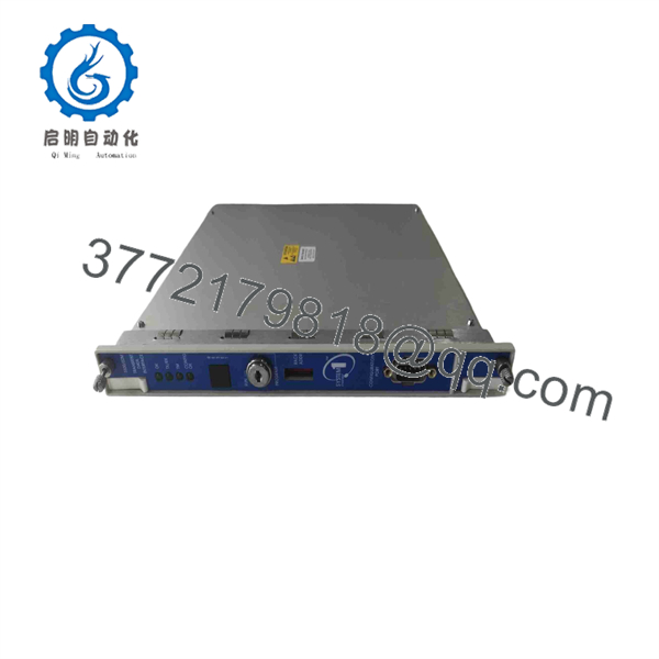
3500/22M 138607-01
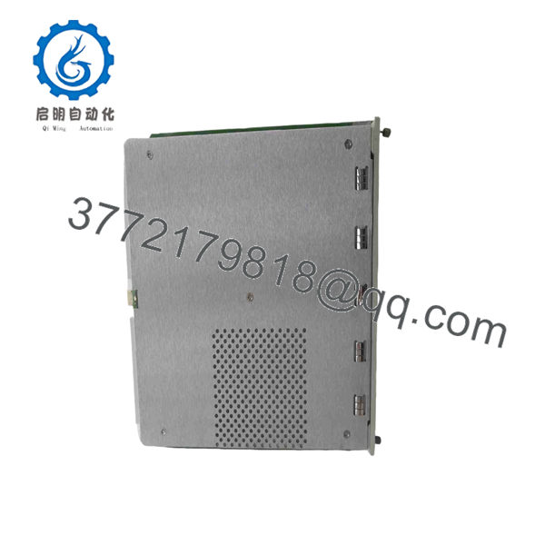
3500/22M 138607-01
Installation & Configuration Guide
Stage 1 — Pre-Installation Preparation
Estimated time: 15–20 minutes
- Confirm the replacement marking is exactly 138607-01.
- Verify that the rack is a compatible 3500 system and identify the TDI slot adjacent to the power supplies.
- Record the installed rear I/O module part number, such as 146031-01 or 146032-01.
- Record the existing firmware/configuration information before replacement.
- Back up the applicable 3500 rack configuration.
- Record current System 1 communication settings and network parameters.
- Apply LOTO where required by the plant procedure.
- Prepare an ESD strap, appropriate screwdriver, labels, multimeter, and the applicable 3500/22M documentation.
⚠️ Do not assume that replacing the front TDI card also replaces the rear communication I/O module. The 138607-01 and the rear I/O assembly are separate components.
Stage 2 — Removing the Old Module
Estimated time: 10–15 minutes
- Place the rack in the approved maintenance state.
- Confirm whether the installed power architecture permits removal without interrupting protection functions.
- Disconnect the applicable network/configuration connections according to the rack procedure.
- Release the front-panel retaining hardware.
- Carefully withdraw the existing TDI module.
- Inspect the card edge, backplane connector, retaining hardware, and adjacent modules.
- Record the removed module’s exact part number and revision.
⚠️ If the rack is operating with a single power supply or is providing an active machinery-protection function, do not remove the TDI without following the approved maintenance procedure.
Stage 3 — Installing the 138607-01
Estimated time: 10–15 minutes
- Verify the replacement module is 3500/22M 138607-01.
- Inspect the connector and module guides for damage.
- Align the module with the correct TDI slot.
- Insert the module carefully into the rack backplane.
- Secure the front-panel retaining hardware.
- Verify that the associated rear I/O module is correctly seated and connected.
- Reconnect the Ethernet or other approved communication connection.
- Confirm that no neighboring module was disturbed during installation.
⚠️ Do not force the module into the rack. Misalignment can damage the backplane connector.
Stage 4 — Power-On & Testing
Estimated time: 20–30 minutes
- Restore power according to the approved 3500 maintenance procedure.
- Check the front-panel OK indication.
- Verify the communication status indicators.
- Confirm the rack reports a valid configuration.
- Connect using the applicable 3500 configuration software.
- Verify the TDI is recognized with the correct hardware identity.
- Confirm communication between the rack and System 1 where applicable.
- Verify that monitoring modules are supplying expected steady-state values.
- If transient acquisition is configured, perform an approved functional test rather than generating an uncontrolled machine event.
- Record the module revision, configuration, communication status, and commissioning results.
The 3500/22M front panel provides status indications including OK, TX/RX, TM, and CONFIG OK, which are useful during commissioning and troubleshooting.
FAQ
Q1. What is the Bently Nevada 3500/22M 138607-01?
It is the Standard Transient Data Interface (TDI) Module for the Bently Nevada 3500 Machinery Protection System. It interfaces the rack with compatible configuration and condition-monitoring software while collecting rack data.
Q2. Is 138607-01 the same as the complete 3500/22M assembly?
Not necessarily. 138607-01 identifies the standard TDI module, while the rear communication I/O module is a separate assembly. For example, 146031-01 is the 10Base-T/100Base-TX copper I/O module listed for the 3500/22M.
Q3. Can 138607-01 communicate with System 1?
Yes. The 3500/22M is designed to interface the 3500 monitoring system with System 1 Condition Monitoring and Diagnostic Software and 3500 System Configuration Software. External Ethernet communication is provided through the associated TDI I/O module.
Q4. Can I replace 138607-01 with 288055-01?
Do not treat this as an unconditional plug-and-play substitution. Current supplier documentation identifies 288055-01 as a replacement for the older 138607-01, but the complete rack hardware, I/O configuration, software compatibility, and installation requirements must be checked before migration.
Q5. Does 138607-01 itself provide the Ethernet connector?
The external network connection is associated with the rear TDI I/O module. The standard configuration uses 146031-01 for 10Base-T/100Base-TX copper Ethernet, while 146032-01 provides 100Base-FX fiber connectivity.
Q6. Does every 3500/22M 138607-01 support high-resolution transient data automatically?
No. Static data capture is standard, while dynamic and high-resolution transient acquisition depends on the configured options and system setup. Do not infer the enabled data-capture capability from the part number alone.
Q7. What should be verified before purchasing a replacement?
Verify the exact 138607-01 part number and revision, the existing rear I/O module, rack configuration, firmware/software compatibility, Ethernet or fiber interface, and required transient-data functions. If the application is being migrated to newer 3500 hardware, confirm the proposed replacement against the current OEM compatibility documentation rather than assuming electrical and software equivalence.



