
 WhatsApp: +86 16626708626
 Email:
  Phone: +86 16626708626
Description
3. Key Technical Specifications
| Parameter | Value |
|---|---|
| Product Type | Transient Data Interface (TDI) Module |
| System | Bently Nevada 3500 Series |
| Installation Slot | Slot adjacent to rack power supplies |
| Communication | 10/100Base-T Ethernet, 100Base-FX Fiber (depending on configuration), USB |
| Serial Port | RS-232, up to 115.2 kbaud |
| Typical Power Consumption | Approximately 10.5 W |
| Operating Temperature | -30 °C to +65 °C |
| Storage Temperature | -40 °C to +85 °C |
| Humidity | 95% RH, non-condensing |
| Hot Swap | Supported within compatible 3500 system architecture |
| Compatible Software | System 1 Condition Monitoring, 3500 Configuration Software |
| Compatible Modules | 3500/40M, 3500/42M and other M-Series monitors |
Verify the exact communication option installed on your unit before deployment, as different ordering codes may provide copper Ethernet, fiber Ethernet, or both.
4. Product Introduction
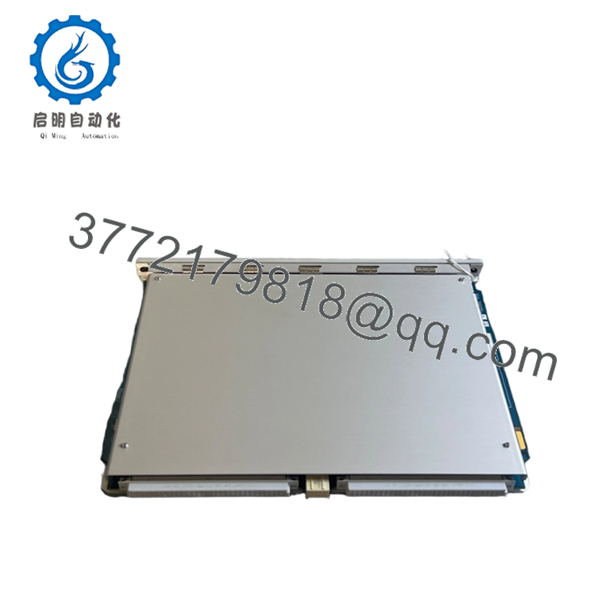
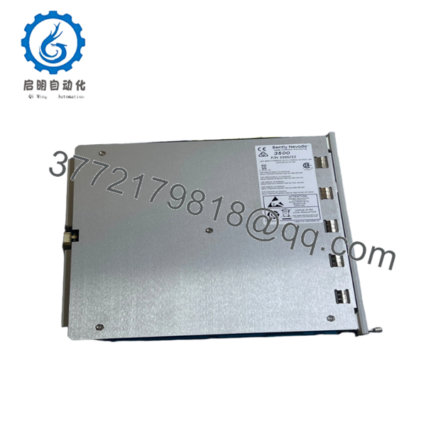
The Bently Nevada 3500-22M 288055-01N is the Transient Data Interface (TDI) module used in the 3500 Machinery Protection System. It serves as the primary communication gateway between the rack and host software, collecting both steady-state and transient waveform data from M-Series monitoring modules.
Unlike the earlier Rack Interface Module (RIM), the 3500-22M integrates rack communication with transient data collection. Plants using System 1 software typically select this module because it supports vibration diagnostics, waveform capture, event recording, and remote configuration while reducing additional communication hardware requirements.

- 3500-22M 288055-01N
- 3500-22M 288055-01N
5. Installation & Configuration Guide
Stage 1 — Pre-Installation Preparation (10 minutes)
⚠️ Safety First
- Notify operations of scheduled downtime.
- Place rotating equipment in a safe operating state.
- Apply Lock-Out/Tag-Out (LOTO).
- Remove rack power.
- Wait at least 5 minutes for internal capacitors to discharge.
Tools Required
- ESD wrist strap
- PH1 screwdriver
- Fluke 115 or equivalent multimeter
- Wire identification labels
- Smartphone for documentation
- Laptop with 3500 Configuration Software
Data Backup
- Export current rack configuration.
- Record IP address and network settings.
- Save System 1 database if applicable.
- Photograph all wiring and communication connections.
- Record installed firmware revision.
Stage 2 — Removing the Existing Module (5 minutes)
- Remove the rack front cover.
- Label all communication cables.
- Disconnect Ethernet, fiber, USB or serial connections.
- Release the locking mechanism.
- Pull the module straight out.
Inspect:
- Rack connector
- Backplane pins
- Dust accumulation
- Bent contacts
⚠️ Do not discard the original module until the replacement has completed functional testing.
Stage 3 — Installing the Replacement Module (10 minutes)
- Wear an ESD wrist strap.
- Confirm part number 3500-22M 288055-01N matches the required configuration.
- Verify communication option (Copper/Fiber).
- Slide the module evenly into the rack.
- Ensure the locking tabs fully engage.
- Reconnect all communication cables.
Self Checklist
- ☑ Correct model number
- ☑ Module fully seated
- ☑ Connectors secured
- ☑ Network cable installed
- ☑ Fiber polarity verified (if applicable)
Stage 4 — Power-On & Functional Testing (10–15 minutes)
Before Applying Power
- Measure the rack 24 V supply for shorts.
- Confirm rack power supply health.
Startup Procedure
- Energize the rack.
- Observe module LEDs.
- Verify the RUN indicator becomes green.
- Connect using 3500 Configuration Software.
- Confirm firmware revision.
- Verify rack communication.
- Confirm all monitor modules appear online.
- Verify waveform collection in System 1.
- Perform a functional communication test.
⚠️ Troubleshooting
Solid ERR LED
- Firmware incompatibility
- Unsupported hardware revision
- Corrupted configuration
No Ethernet Communication
- Incorrect IP address
- Incorrect subnet
- Fiber TX/RX reversed
- Network switch configuration
Module Not Detected
- Backplane connector not fully seated
- Rack power issue
- Incorrect rack slot
Engineer’s Installation Notes
After commissioning dozens of 3500 systems, the issue that causes the most unnecessary downtime is not hardware failure—it’s replacing the TDI without documenting the original network configuration. Before removing the module, save the rack configuration and record the firmware revision. That five-minute task can save hours of troubleshooting later.
Another common mistake is assuming every 3500-22M has identical communication hardware. Verify whether your installed unit uses copper Ethernet, fiber Ethernet, or both before ordering a replacement. The base model number alone does not always identify every communication option.
6. Frequently Asked Questions (FAQ)
Q1. Can I hot-swap the 3500-22M module?
The 3500 architecture supports hot-swappable modules under supported conditions. Even so, many maintenance teams still schedule a maintenance window because communication with System 1 may be interrupted during replacement. Always follow your site’s maintenance procedures before relying on hot swap capability.
Q2. Will removing this module erase my monitoring configuration?
No. Configuration is primarily stored within the system architecture rather than the TDI itself. However, always back up the rack configuration before maintenance. Never assume the existing configuration can be recovered after an unexpected failure.
Q3. Is 3500-22M 288055-01N obsolete?
The 3500 platform remains widely deployed in power generation, oil and gas, petrochemical, and heavy industry. Some specific revisions are no longer manufactured in high volumes, so new surplus inventory is more common than fresh factory production. Stock availability varies by hardware revision.
Q4. Why are surplus units often less expensive than OEM pricing?
Many surplus modules originate from project overruns, cancelled capital projects, or unused maintenance inventory. A genuine new-surplus module can offer substantial savings while remaining unused. Buyers should request serial-number verification, inspection records, and functional test reports before purchase.
Q5. What should I verify before ordering?
Check:
- Exact part number
- Hardware revision
- Firmware revision
- Communication interface (Copper or Fiber)
- Rack compatibility
- Required software version
These details prevent most compatibility issues.
Q6. What quality checks should a reputable supplier perform?
A thorough incoming inspection should include:
- OEM serial number verification
- Visual inspection for corrosion, scratches, or rework
- Functional testing in a genuine 3500 rack
- Ethernet communication verification
- Continuous load testing for at least 24 hours
- Insulation resistance testing
- Firmware documentation
- ESD-safe packaging with QC sign-off
A supplier should also be willing to provide test photos or videos upon request. Verified functional testing provides far more confidence than a simple statement that the unit is “working.”



