
 WhatsApp: +86 16626708626
 Email:
  Phone: +86 16626708626
Description
Key Technical Specifications
| Parameter | Specification |
| Manufacturer | Bently Nevada / Baker Hughes |
| Model Series | 3500/32 4-Channel Relay System |
| Rear I/O Part Number | 125720-01 |
| Associated Main Card | 3500/32 Front Control Module (125712-01 / 149986-02) |
| Terminal Connection Type | Euro-style internal screw termination block |
| Channel Count | 4 independent relay output terminal channels |
| Maximum Voltage | 250 VAC RMS / 125 VDC |
| Maximum Current | 5 A @ 120/240 VAC; 5 A @ 30 VDC; 0.2 A @ 125 VDC |
| Arc Suppression | Integrated 250 Vrms suppressors on all channels |
| Relay Sealing | Epoxy-sealed relay environment |
| Rack Slot Location | Full-height rear chassis slot directly behind front 3500/32 module |
| Dimensions (H x W x D) | 241 mm x 24.4 mm x 99.1 mm (9.5 in x 0.96 in x 3.9 in) |
| Weight | 0.4 kg (1.0 lb) |
Product Introduction & Supply Chain Strategy
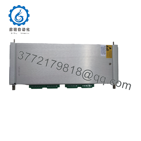
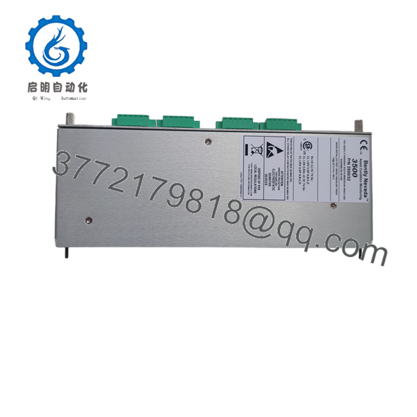
The Bently Nevada 3500/32 125720-01 is the full-height rear I/O card that houses the physical screw-terminal connections for the 3500/32 4-channel relay system. Installed in the back of the 3500 rack directly behind the front control card (125712-01), it provides epoxy-sealed contact terminations and onboard 250 Vrms arc suppressors to route trip interlocks directly to plant Safety Instrumented Systems (SIS).
Maintaining verified New Surplus 125720-01 rear modules in critical stock avoids catastrophic machine shutdown delays during hardware swap-outs. Reusing second-hand or refurbished terminal cards risks high electrical resistance, stripped terminal screws, or pitted contact pins, which can fail to break a safety loop during an emergency or cause accidental open-circuit trips.
Installation & Configuration Guide
Stage 1: Pre-Installation (Prep & Safety)
- Ensure the field trip loops connected to the rear module are isolated or placed in manual bypass at the main control room panel.
- Put on a grounded anti-static wrist strap connected to the cabinet ground.
- Label all incoming field wires (Normally Open, Normally Closed, Common for each channel) to prevent terminal pinout mix-ups during re-wiring.
Stage 2: Removal
- Unplug or unbolt the green terminal block headers from the rear 125720-01 panel using a flat-head terminal screwdriver.
- Loosen the upper and lower captive screws on the 125720-01 faceplate.
- Pull the module straight back out of the chassis slot using the ejection handles, avoiding lateral twist that could damage adjacent backplane pins.
Stage 3: Installation (Clone & Seat)
- Inspect the card edge gold fingers on the new 125720-01 board for contamination, debris, or damaged traces.
- Align the 125720-01 module with the rear card guides corresponding directly to the slot containing the front 3500/32 main module.
- Slide the card in firmly until the rear panel sits flush against the 3500 chassis frame.
- Tighten the captive mounting screws securely to maintain continuous chassis shield grounding.
Stage 4: Power-On & Testing
- Reinsert the green terminal connectors into the 125720-01 board.
- Verify contact continuity across channels using a digital multimeter while performing a software channel test from the front 3500/32 card.
- Remove safety bypasses and return the trip interlock loop to full active protection mode.

- 3500/32 125720-01
- 3500/32 125720-01
Firmware/Software Versions & Upgrade Notes
- Passive Architecture: The 125720-01 module is a passive rear interface board containing field wiring terminals, contact traces, and arc suppression circuits. It holds no digital microprocessor or firmware.
- System Mapping: Relay operation settings (Normally Energized vs. Normally De-energized and AND/OR voting logic) are set via the front-facing 3500/32 card using 3500 System Configuration Software.
- Compatibility Notice: The 125720-01 is designed specifically for standard internal termination systems. Verify whether your installation uses standard internal termination (125720-01) or hazardous area / external termination variants (such as 125720-02) before performing a hardware swap.
Frequently Asked Questions (FAQ)
Is this 125720-01 module genuinely new, or is it a pulled/refurbished part?
This product is a Brand New Surplus unit. It is not used, not pulled from a decommissioned plant, and not refurbished. All modules undergo strict quality verification to ensure OEM-level performance. Original anti-static packaging is retained and opened solely for physical verification and anti-static inspection before delivery.
What is the difference between the 125712-01 and the 125720-01 part numbers?
The 125712-01 is the front main control module containing the primary processing logic and status LEDs, while the 125720-01 is the rear I/O module containing the physical terminal blocks for external field wiring. A complete 3500/32 relay channel slot requires both modules to function.
Does the 125720-01 rear module include built-in arc suppression?
Yes, the 125720-01 module comes equipped with factory-installed 250 Vrms arc suppressors as standard on all output channels. This protects the relay contacts from high-voltage inductive spikes caused by solenoids, motor starters, or trip coils.
What is the difference between 125720-01 and 125720-02?
The 125720-01 is the standard 4-channel relay I/O module designed for general industrial and functional safety systems. The 125720-02 option is specialized for hazardous area installations requiring specific agency approvals or intrinsic safety barrier interface capabilities.
Can I disconnect field wiring from the 125720-01 without turning off the entire 3500 rack?
Yes, the green terminal headers can be unplugged directly from the rear card faceplate. However, ensure your field trip circuit is placed in a safe or bypassed state before unplugging, as disconnecting a Normally Energized (fail-safe) relay loop will open the circuit and trip connected equipment.
What warranty coverage is included with this New Surplus I/O module?
We provide a comprehensive 1-year replacement warranty on all New Surplus Bently Nevada hardware. If the 125720-01 module experiences any electrical fault or terminal defect within 12 months under standard operating conditions, we replace the unit immediately from available stock.



