
 WhatsApp: +86 16626708626
 Email:
  Phone: +86 16626708626
Description
Key Technical Specifications
| Parameter | Value |
|---|---|
| Manufacturer | Bently Nevada |
| Model | 3500/33-01 |
| Product Type | 16-Channel Relay Module |
| Series | 3500 Machinery Protection System |
| Relay Outputs | 16 independently programmable SPDT relays |
| Typical Power Consumption | 5.8 W |
| Relay Logic | AND / OR voting logic |
| Configuration Software | 3500 Rack Configuration Software |
| Installation | Full-height front module for 3500 rack |
| Rack Position | Any slot to the right of the Transient Data Interface (TDI) |
| Relay Mode | Normally Energized (NE) or Normally De-Energized (NDE), switch selectable |
| Typical Applications | Alarm annunciation, equipment shutdown, process interlocks, machinery protection |
| Compliance | Supports installations designed to API 670 requirements when integrated into a complete 3500 system |
Product Introduction
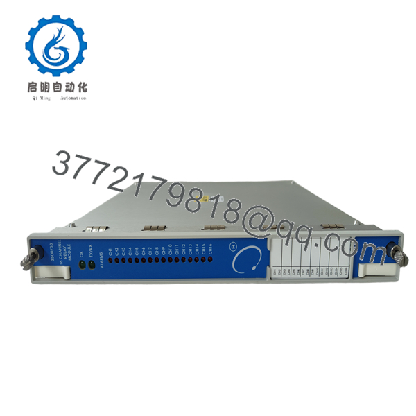
The Bently Nevada 3500/33-01 is a 16-Channel Relay Module designed for the 3500 Machinery Protection System. It provides sixteen independently programmable relay outputs that convert alarm conditions generated by vibration, position, temperature, or process monitoring modules into external control signals for shutdown systems, annunciators, and plant control equipment.
Each relay channel supports configurable Alarm Drive Logic using AND/OR voting functions. Inputs may include Alert, Danger, Not OK, or measured variables from any monitor installed in the rack, allowing engineers to implement customized protection strategies without additional external relay logic hardware.
Installation & Configuration Guide
Stage 1 – Pre-Installation Preparation (10 Minutes)
⚠️ Safety First
- Notify operations before scheduled downtime.
- Perform Lockout/Tagout procedures.
- Remove rack power and allow at least five minutes for stored energy to discharge.
- Wear an ESD wrist strap before handling the module.
Required Tools
- Phillips screwdriver
- ESD wrist strap
- Digital multimeter
- Wire identification labels
- Smartphone for recording wiring and switch settings
Before Removal
- Back up the complete 3500 rack configuration.
- Record firmware revisions.
- Photograph wiring and terminal connections.
- Document relay assignments and logic.
Stage 2 – Remove the Existing Module (5 Minutes)
- Remove the rack front cover.
- Label every field connection.
- Disconnect wiring without forcing terminal blocks.
- Release the retaining mechanism.
- Pull the module straight out to protect the backplane connector.
⚠️ Keep the original module until the replacement has completed functional testing.
Stage 3 – Install the New Module (10 Minutes)
- Verify the replacement is 3500/33-01 with the correct output option.
- Inspect the rack connector for bent pins or contamination.
- Insert the module completely into the guide rails.
- Lock the retaining tabs.
- Reconnect all field wiring.
Installation Checklist
- ✅ Model verified
- ✅ Module fully seated
- ✅ Wiring confirmed
- ✅ Retaining mechanism locked
Stage 4 – Power-Up & Commissioning (10 Minutes)
- Verify the 24 V supply is free from shorts.
- Apply power to the rack.
- Confirm the OK LED illuminates normally.
- Verify communication activity through the TX/RX indicator.
- Open the 3500 Rack Configuration Software.
- Restore or verify the relay configuration.
- Simulate Alert and Danger alarms to verify each relay output.
⚠️ If communication fails after installation, verify firmware compatibility and the downloaded rack configuration before replacing additional hardware.

- 3500/33-01
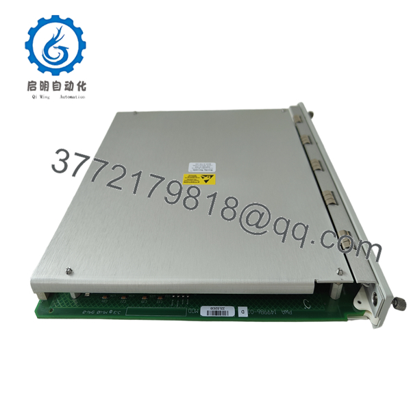
- 3500/33-01
Frequently Asked Questions
Q1. Can the 3500/33-01 be hot-swapped?
No. The module is not designed for hot replacement. Always remove rack power before installation to prevent backplane damage or unintended relay operation.
Q2. What is the difference between the 3500/33-01 and the spare control module 149986-01?
The 3500/33-01 is a complete 16-channel relay module ordering configuration, while 149986-01 is the spare relay control module used for servicing or replacement within the same product family.
Q3. How many relay outputs are available?
The module provides 16 independently programmable SPDT relay outputs, each supporting configurable Alarm Drive Logic and voting functions.
Q4. Which signals can activate the relays?
Relay outputs can be driven by Alert, Danger, Not OK status, or selected measured variables from any compatible monitor channel installed in the same 3500 rack.
Q5. Does replacing the module erase machine protection settings?
No. The rack configuration is maintained separately. However, experienced engineers always create a complete configuration backup before replacing any module to minimize commissioning time.
Q6. What is the most common installation mistake?
The most frequent issue is restoring the hardware without verifying the downloaded relay logic. Incorrect Alarm Drive Logic or voting configuration often causes unexpected relay behavior even though the module itself is functioning correctly.
Q7. Is the 3500/33-01 still available?
Yes. Although it belongs to a mature machinery protection platform, the 3500/33-01 remains widely available through industrial automation spare-parts suppliers as new surplus or tested inventory, depending on stock availability.



