
 WhatsApp: +86 16626708626
 Email:
  Phone: +86 16626708626
Description
Key Technical Specifications
| Parameter | Value |
|---|---|
| Manufacturer | Bently Nevada |
| Model | 3500/33 149986-01 |
| Product Type | Spare 16-Channel Relay Control Module |
| Series | 3500 Machinery Protection System |
| Relay Outputs | 16 independently programmable channels |
| Relay Type | SPDT (Single-Pole Double-Throw) |
| Power Consumption | 5.8 W typical |
| Configuration Software | 3500 Rack Configuration Software (v3.3 or later) |
| Rack Installation | Full-height front slot, right of the TDI module |
| Logic Functions | AND/OR alarm drive logic |
| Typical Applications | Alarm annunciation, machine shutdown, process interlocking |
| Certifications | Hazardous-area approvals available depending on ordering option |
Product Introduction
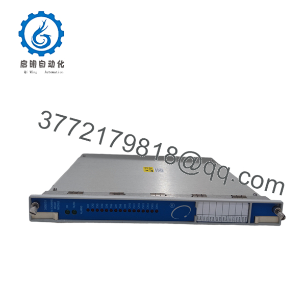
The Bently Nevada 3500/33 149986-01 is the Spare 16-Channel Relay Control Module used in the 3500 Machinery Protection System. It manages up to sixteen programmable relay outputs that convert machine protection events into external alarm, shutdown, and control signals for turbines, compressors, generators, pumps, and other rotating equipment.
Each relay channel can be programmed independently using configurable AND/OR voting logic. The module accepts alarm, Danger, Not-OK, and measured-variable inputs from any monitor installed in the rack, allowing engineers to build customized shutdown and protection strategies without external relay logic hardware.
Installation & Configuration Guide
Stage 1 – Pre-Installation Preparation (10 Minutes)
⚠️ Safety First
- Notify plant operations of the planned shutdown.
- Apply Lockout/Tagout procedures.
- Remove rack power and wait at least five minutes.
- Wear an ESD grounding strap.
Required Tools
- ESD wrist strap
- Phillips screwdriver
- Digital multimeter
- Wire identification labels
- Smartphone for wiring documentation
Before Removing the Existing Module
- Back up the complete 3500 rack configuration.
- Record firmware and software revisions.
- Photograph all terminal wiring.
- Save relay logic assignments.
Stage 2 – Remove the Existing Module (5 Minutes)
- Open the rack front cover.
- Label every field connection.
- Disconnect the wiring carefully.
- Release the retaining mechanism.
- Pull the module straight out without twisting.
⚠️ Keep the original module available until the replacement has completed commissioning successfully.
Stage 3 – Install the New Module (10 Minutes)
- Confirm the replacement part number is 149986-01.
- Inspect the rack connector for contamination or bent contacts.
- Insert the module until fully seated.
- Lock the retaining clips.
- Reconnect all wiring.
Installation Checklist
- ✅ Correct part number
- ✅ Module fully seated
- ✅ Wiring verified
- ✅ Connectors secured
Stage 4 – Power-Up & Commissioning (10 Minutes)
- Check for power supply shorts before energizing.
- Apply rack power.
- Verify the OK LED remains illuminated.
- Confirm TX/RX activity.
- Open the 3500 Rack Configuration Software.
- Download or verify the saved configuration.
- Simulate Alert and Danger conditions to verify relay operation.
⚠️ A communication fault after installation is frequently caused by an incorrect configuration or software revision rather than a hardware defect.

- 3500/33 149986-01
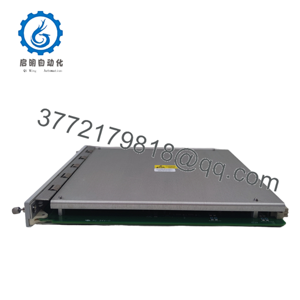
- 3500/33 149986-01
Frequently Asked Questions
Q1. Can the 149986-01 be replaced while the rack is energized?
No. The 3500/33 is not intended for hot swapping. Always remove power before replacing the control module to avoid damage to the rack or unexpected relay operation.
Q2. What does the 149986-01 actually control?
The 149986-01 is the Relay Control Module. It processes alarm information from the monitoring system and commands the associated relay output module to operate external alarms, shutdown devices, or process interlocks.
Q3. How many relay outputs are available?
The module supports 16 independently programmable relay channels, each capable of using configurable AND/OR alarm drive logic.
Q4. Which software is required for configuration?
The module requires 3500 Rack Configuration Software version 3.3 or later for programming and commissioning.
Q5. Is the 149986-01 still available?
Although the 3500 platform remains widely deployed, the 149986-01 is generally supplied as a spare part. New surplus and tested inventory are commonly available through industrial automation suppliers, while availability depends on current stock.
Q6. What is the most common commissioning issue?
Firmware or configuration mismatches are encountered more often than hardware failures. Before removing the existing module, save the rack configuration and document all relay logic. Restoring the original configuration typically resolves startup issues much faster than replacing additional hardware.
Q7. Where is the module installed?
The 3500/33 occupies a full-height front slot in the 3500 rack and is installed in any available slot to the right of the Transient Data Interface (TDI) Module. Multiple 3500/33 modules may be installed in the same rack when additional relay outputs are required.



