

 WhatsApp: +86 16626708626
 Email:
  Phone: +86 16626708626
Description
Key Technical Specifications
| Parameter | Value / Specification |
| Channel Count | 4 independent proximity channels |
| Supported Transducers | Bently Nevada 3300, 3300 XL, or 7200 series Proximitor systems |
| Input Impedance | 10 kΩ standard input resistance |
| Configurable Functions | Radial vibration, Thrust position, Eccentricity, Differential expansion, REBAM |
| Buffered Outputs | Front-panel coaxial connectors (short-circuit protected) |
| Transducer Supply Voltage | −24 Vdc constant power per channel |
| Accuracy Matrix | Direct/Gap values within ±0.33% of full-scale typical |
| Power Consumption | 7.7 W typical operational load |
| Signal Resolution | 12-bit internal conversion architecture |
| Operating Temperature | −30 to +65 °C (−22 to +149 °F) |
Product Introduction & Supply Chain Strategy
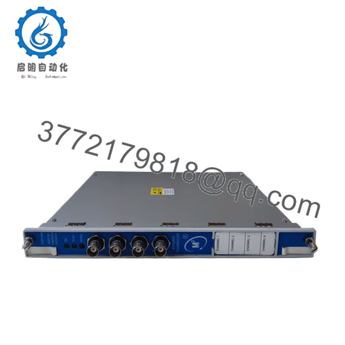
The Bently Nevada 3500/40 is a foundation-level four-channel Proximitor monitor board that acts as the primary defense line for critical rotating machinery. By directly interfacing with proximity transducer systems, the module continuously updates real-time parameters like radial shaft vibration, axial thrust alignment, casing eccentricity, and mechanical expansion variations. When monitored thresholds breach safe parameters, the module executes immediate hardware logic loops to trigger protective downstream relay assemblies, preserving high-value turbomachinery from destructive mechanical faults.
Carrying this specific module as a New Surplus asset forms the baseline of an ROI-driven MRO (Maintenance, Repair, and Operations) strategy. Because a 3500/40 card handles critical trip loops, micro-cracks or drying electrolytic capacitors inside refurbished alternatives pose an extreme operational hazard; a single card failure can trigger a cascading plant shutdown. By embedding an unused, factory-sealed surplus monitor directly into your onsite critical storage path, you eliminate extensive factory lead times and bypass the hidden failure vectors of second-hand units, striking an ideal balance between lifecycle risk management and procurement cost efficiency.
Installation & Configuration Guide
Stage 1: Pre-Installation (Prep & Safety)
- Verify the specific slot destination inside the 3500 rack and review your plant safety logs to isolate the associated trip relay circuits.
- Put on a grounded ESD wrist strap, snapping the lead onto the bare metal earthing ground lug of the 3500 panel.
- Open the 3500 Rack Configuration utility on your engineering workstation and download a complete configuration backup (.w1 file) matching the current slot address.
Stage 2: Removal
- Loosen the upper and lower integrated captive mounting screws on the existing 3500/40 front panel.
- If moving to the rear, disconnect the fieldside I/O wiring terminal head block entirely without snapping individual core wires out of their screw terminal channels.
- Unlatch the injection/ejection hooks on the front panel and guide the card horizontally out along the channel slide boundaries, maintaining linear alignment to avoid damaging any backplane multi-pin connections.
Stage 3: Installation (Clone & Seat)
- Unbox the new surplus 3500/40 and set any internal hardware jumper matrices (such as Keyphasor supply links) to mirror the removed card’s original footprint.
- Slide the module squarely along the chassis card guides towards the backplane.
- Apply steady pressure against the face edges until the card slides flush against the structural channel stops, then anchor the card completely via the captive screws.
Stage 4: Power-On & Testing
- Re-seat the pre-wired field termination block onto the corresponding matching rear I/O card.
- Re-energize the rack frame slot. Monitor the front-panel status cluster: the OK LED must turn solid green while the Bypass lamp will cycle active until configuration delivery.
- Push the archived software configuration data package down to the rack slot over your communication bridge, confirming that the TX/RX light responds and all diagnostic errors clear.

- 3500/40
Firmware/Software Versions & Upgrade Notes
The 3500/40 series has undergone various firmware revisions across its manufacturing history, with modern iterations falling under the “M” designation (3500/40M) to indicate enhanced transient data processing compatibility. Standard legacy 3500/40 modules rely on firmware sets that must balance directly with the firmware running on your main 3500/22M Transient Data Interface (TDI) module.
When performing a field swap with a surplus module, check that the firmware embedded on the incoming card does not exceed or fall below the minimum threshold required by your baseline 3500 Rack Configuration software version. An unresolved firmware mismatch will prevent the configuration utility from binding with the card, leaving the slot permanently in a Bypass or Error state. Always cross-reference your configuration software documentation before replacing active machinery protection components.
Frequently Asked Questions (FAQ)
What is the mechanical difference between a 3500/40 and a 3500/40M?
The “M” designation stands for “Modified/Enhanced” processing capability. While both models monitor four proximity probe channels and handle identical field wiring inputs, the 3500/40M features updated digital signal processing chips that allow it to continuously stream static parameters and dynamic waveform samples across the backplane to the TDI module for deep diagnostic software analysis. The 3500/40M acts as a direct, drop-in functional replacement for the older, non-M 3500/40 version.
Is this 3500/40 monitor card an authentic, unenergized unit?
Yes. This is a Brand New Surplus item, sourced directly from unutilized industrial inventory overstocks. It has never been mounted in a field rack, never experienced field runtime, and has never undergone component-level soldering repairs. It is completely clean and preserved in ESD-safe protective packaging.
Why shouldn’t we save budget by purchasing a refurbished 3500/40 card instead?
Machinery protection hardware is your final line of insurance against multi-million dollar rotating asset destruction. Refurbished cards are used assets that have already undergone years of thermal loading, making them susceptible to hidden solder joint fractures and internal component degradation. A New Surplus card eliminates the structural failure risks inherent to used electronics while matching your budget optimization parameters.
Do I need to re-calibrate my proximity probes after sliding this new card in?
No, you do not need to alter the physical installation layout of your field proximity probes. However, you must verify that the sensor configuration parameters (e.g., 200 mV/mil scale factor settings for a 3300 XL probe) are downloaded into the new card using the 3500 configuration software to ensure accurate scaling.
Will this card arrive configured for our exact field sensors?
Surplus cards ship in their clean, unconfigured factory default states to maximize application flexibility. You will need to mount the board, connect via your engineering interface, and push your plant’s specific configuration profile (.w1 file) to set the channel pairs for your precise application (such as thrust position or radial vibration).



