
 WhatsApp: +86 16626708626
 Email:
  Phone: +86 16626708626
Description
Key Technical Specifications
| Parameter | Specification Value |
| Manufacturer | Bently Nevada (Baker Hughes) |
| Part Number | 135489-03 / PWA 135489-03 |
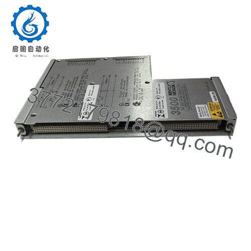
| Module Type | 3500/42M Proximitor Seismic Monitor |
| Channel Count | 4 independent, fully programmable channels |
| Supported Transducers | Proximitor sensors, REBAM acceleration, Seismoprobe, velomitors |
| Signal Processing | Radial vibration, thrust position, eccentricity, differential expansion |
| A/D Conversion | 24-bit high-resolution delta-sigma conversion |
| Buffered Outputs | 4 coaxial front panel connectors (1 per channel, short-circuit protected) |
| Current Outputs | 4 to 20 mA DC proportional to selected channel configurations |
| Operating Temperature | −30 to +65 °C (−22 to +149 °F) |
Product Introduction & Supply Chain Strategy
The Bently Nevada 135489-03 serves as the 3500/42M Proximitor Seismic Monitor, a core processing component within the 3500 Machinery Protection System. This module accepts input from up to four displacement, velocity, or acceleration transducers, converting the signals into real-time variables like shaft vibration, thrust positioning, and casing eccentricity. Crucially, it compares these values against digital alert limits, communicating directly with the rack backplane to drive trip relays and execute emergency asset shutdowns on critical industrial turbomachinery.
Securing the 135489-03 under a New Surplus procurement model is an essential action to control Total Cost of Ownership (TCO) on critical machinery. Because the 3500 platform is a legacy architecture with restricted factory allocations, relying on cheap refurbished boards introduces critical failure vectors: aged analog-to-digital converters can experience signal drift, causing missed events or false plant trips. Holding 1–2 factory-sealed units on-site serves as an indispensable insurance policy, protecting your plant against extended stock-out incidents on major generation and processing assets.

- 135489-03
Installation & Configuration Guide
Stage 1: Pre-Installation (Prep & Safety)
- Completely isolate the target 3500 monitor rack power using approved plant lock-out/tag-out safety rules.
- Put on a grounded, static-dissipative ESD wrist strap, attaching the clip to an unpainted metal section of the structural enclosure frame.
- Access the system design documents to confirm the correct hardware jumper settings required for your specific sensor type (e.g., proximity probe vs. velomitor).
Stage 2: Removal
- Loosen the upper and lower faceplate screws on the malfunctioning 3500/42M monitor using a standard flathead tool.
- Pull the upper and lower ejector levers outward to detach the board’s internal contacts from the rack backplane connector block.
- Slide the card straight out along the chassis tracks, holding it only by the plastic faceplate and board edges to prevent surface contamination.
Stage 3: Installation (Clone & Seat)
- Unbox the new surplus 135489-03 card within an ESD-protected zone and verify that all rear pins are straight.
- Align the internal configuration jumpers on the new board to mirror the original unit’s settings exactly.
- Guide the module into the empty chassis track, sliding it smoothly inward until the rear pins press completely into the motherboard socket. Hand-tighten the upper and lower faceplate screws.
Stage 4: Power-On & Testing
- Restore power to the 3500 rack and monitor the initialization diagnostic sequence on the front panel LEDs.
- Confirm that the green “OK” LED turns on steadily, indicating that the internal self-test completed without any component errors.
- Connect your configuration PC to the rack interface module to upload the channel settings and verify that the live sensor gap voltages match design parameters.
Firmware/Software Versions & Upgrade Notes
The 135489-03 3500/42M card handles signal processing and alarm timing through onboard firmware chips. Hardware revisions—such as the change from legacy 3500/42 modules to the modern “M” enhanced-frequency variants—dictate compatible options inside the 3500 Rack Configuration Software.
Before removing a unit, connect locally to read and document the active application firmware version code. When replacing an older card with the 135489-03, ensure your system software release fully supports this specific hardware version. Do not attempt to upgrade or downgrade the module’s firmware mid-stream during a direct replacement action unless it is strictly necessary to match a specific system firmware baseline.
Frequently Asked Questions (FAQ)
Q: Why is this New Surplus module priced higher than used variants on online marketplaces? A: This module is an un-deployed, authentic OEM component preserved in pristine, factory-sealed storage conditions. Used or refurbished options are typically harvested from decommissioned plants and suffer from thermal stress or component degradation, which can compromise critical vibration tracking circuits. Our pricing reflects the market value of secure, unused inventory that guarantees a 10–15 year operating lifespan, eliminating the risk of sudden downtime that can cost thousands of dollars per hour.
Q: Does this 3500/42M module require a corresponding I/O module in the rear of the rack? A: Yes. The 135489-03 is the front-mounted processing card. It must be paired with the correct rear I/O module (such as the 128229-01 standard I/O module or internal barrier options) to connect the field transducer wiring properly.
Q: Can this proximitor seismic monitor be hot-swapped while the turbine is running? A: Yes, the module is hot-swappable, allowing you to change it out without cutting power to the rest of the rack. However, pulling this module will immediately drop all vibration telemetry and alarm detection for those four specific channels. Ensure that any coupled machinery trip interlocks are placed in a safe manual state before removing the hardware.
Q: What is the purpose of the coaxial connectors on the front panel of the card? A: These are buffered outputs that provide clean, unconditioned raw voltage signals for each of the four channels. They allow vibration engineers to connect portable data collectors, oscilloscopes, or dynamic signal analyzers directly to the front of the rack for advanced diagnostic troubleshooting without disrupting normal operations.
Q: Does this module require manual calibration during field installation? A: The card does not require physical manual tuning. All configuration settings, including transducer scale factors, alarm setpoints, and bypass delays, are configured digitally using the 3500 Rack Configuration Software interface during initial commissioning.
Q: What type of warranty protection is supplied with this surplus component? A: We provide a 1-year operational replacement warranty on all New Surplus modules. This warranty covers hardware defects and ensures the module will perform reliably within your active predictive maintenance framework.


