
 WhatsApp: +86 16626708626
 Email:
  Phone: +86 16626708626
Description
Key Technical Specifications
| Parameter | Specification Value |
| Channel Capacity | 4 continuous monitoring channels (configured in pairs) |
| Supported Transducers | Proximitor sensors, Rotary Position Transducers (RPT), DC LVDTs |
| Measurement Functions | Axial (Thrust) Position, Differential Expansion, Case Expansion, Valve Position |
| Input Impedance | 10 kΩ (Proximitor/RPT), 1 MΩ (DC LVDT) |
| Transducer Power Output | -24 V DC (Proximitor/RPT), +15 V DC (DC LVDT) |
| Power Consumption | 7.7 W typical (Position I/O module) |
| Direct Filter Frequency Response | -3 dB cutoff at 1.2 Hz |
| Gap Filter Frequency Response | -3 dB cutoff at 0.41 Hz |
| Measurement Accuracy | Within ±0.33% of full-scale typical (±1.0% maximum) |
| Analog Recorder Outputs | +4 to +20 mA proportional current loop per channel (0 to 600 Ω load) |
| Operating Temperature | −30 °C to +65 °C (−22 °F to +150 °F) |
| Main Module Dimensions | 241.3 mm x 24.4 mm x 241.8 mm (9.50 in x 0.96 in x 9.52 in) |
Product Introduction & Supply Chain Strategy
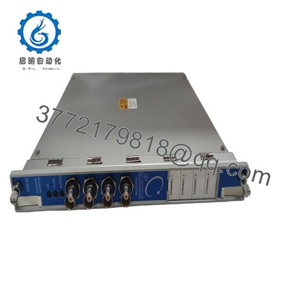
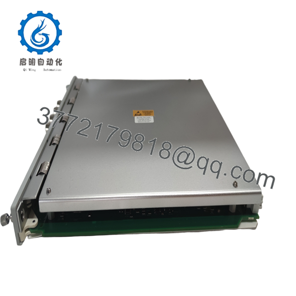
The Bently Nevada 3500/45-01-00 is a 4-channel position monitor that conditions signals from proximity probes, rotary transducers, and DC LVDTs to protect turbomachinery against axial rotor movement and differential casing expansion. It continuously compares position values against user-configured alert and danger setpoints to trigger automated machine trip logic.
Stocking this option -01-00 (Internal Termination I/O) module as a New Surplus spare protects plants from multi-day forced outages during steam turbine or compressor overhaul delays. Sourcing genuine New Surplus ensures original factory tolerances, uncompromised backplane connector pins, and zero component thermal aging, guaranteeing a 10–15 year operational service life.

- 3500/45-01-00
- 3500/45-01-00
Installation & Configuration Guide
Stage 1: Pre-Installation (Prep & Safety)
- Initiate lockout/tagout on connected machinery protection trip outputs.
- Put on an anti-static wrist strap connected directly to cabinet ground.
- Open 3500 Rack Configuration Software and save an archive copy of the active rack configuration (
.350file). - Document the channel paired configurations, transducer scale factors, and wiring terminal pinouts on the rear I/O module.
Stage 2: Removal
- Loosen the upper and lower captive screws on the 3500/45 main monitor card.
- Unlatch the ejector handles simultaneously to disengage the rear edge connectors from the 3500 backplane bus.
- Slide the main module out along the card guide slots and immediately place it into an ESD shielding pouch.
Stage 3: Installation (Clone & Seat)
- Verify the replacement 3500/45 card matches the hardware revision and configuration jumper layout of the removed unit.
- Align the main card edges into the guide rails of the designated rack slot.
- Slide the module in firmly until it seats in the backplane, close both ejector latches, and hand-tighten the top and bottom captive screws.
Stage 4: Power-On & Testing
- Apply system power to the 3500 rack power supplies.
- Verify the front panel OK LED illuminates solid green and the TX/RX LED flashes during backplane polling.
- Inject DC offset test voltages to verify live position readings match software calibration before removing the slot software bypass.
Firmware/Software Versions & Upgrade Notes
- Recommended Firmware: Firmware Revision 1.15 or later (managed via 3500 Rack Configuration Software v4.0 or higher).
- Compatibility Notice: Option -01 specifies the 125808-01 Position I/O Module with Internal Terminations. Ensure the firmware loaded in slot parameter memory matches this I/O type; selecting an AC LVDT or External Termination I/O layout in software will trigger a rack configuration mismatch error (NOT OK LED).
- Upgrade/Downgrade Risk Warning: Do not download new firmware or rack configurations while the turbine is running. Re-flashing forces the 3500/45 module into reset, driving analog outputs to 0 mA and opening system OK relays, which can trigger accidental unit trips if not bypassed.
Frequently Asked Questions (FAQ)
What does the “-01-00” ordering option code represent?
Option -01 specifies the Position I/O Module with Internal Terminations designed for Proximitor, RPT, and DC LVDT inputs. Option -00 indicates standard agency approvals (cNRTLus Class 1, Division 2 / Zone 2 standard).
Is this Bently Nevada 3500/45-01-00 module original and unused?
Yes. We supply exclusively Brand New Surplus units in original OEM anti-static packaging. These cards come from verified inventory overstock, carry no insertion wear on backplane contacts, and pass thorough visual and electrical QC testing.
Why choose New Surplus over lower-priced salvaged modules?
Salvaged or repaired modules often contain degraded tantalum capacitors and thermal stress from years of continuous cabinet operation. Investing 20% to 30% more in New Surplus guarantees 100% factory reliability and eliminates the risk of an unexpected $50,000+ downtime event caused by a failing position card.
Can I monitor both thrust position and case expansion on the same card?
Yes. The 3500/45 programs its 4 channels in pairs. For instance, Channels 1 and 2 can be configured for Axial (Thrust) Position, while Channels 3 and 4 monitor Case Expansion or Differential Expansion. Note that Case Expansion is supported specifically on Channels 3 and 4.
How do I replace this card without tripping the turbine?
Before pulling the card, launch the 3500 Rack Configuration Software, navigate to the 3500/45 slot configuration, and set the module status to Rack Software Bypass. This disables trip relay activation for those 4 channels during hardware swapping.
What warranty is included with this position card?
All New Surplus Bently Nevada modules include a full 1-year replacement warranty, a verified serial number certificate, and a comprehensive pre-shipment QC report.



