
 WhatsApp: +86 16626708626
 Email:
  Phone: +86 16626708626
Description
Key Technical Specifications
| Parameter | Value / Specification |
| Part Number Matrix | 136703-01 (Rear I/O counterpart to 3500/50 main card) |
| Channel Capacity | 2 independent speed/pulse channels |
| Protection Type | Integral intrinsic safety isolation barriers (Internal Barriers) |
| Termination Design | Internal fixed terminal blocks (Euro style) |
| Transducer Options | Proximity probes, passive magnetic pickups, or active speed sensors |
| Maximum Frequency | 30 kHz signal bandwidth capability |
| Input Voltage Range | 0 to 55 Vdc operational envelope |
| Dimensions | 24.13 cm x 2.44 cm x 10.31 cm (Full-height slot profile) |
| Weight | 0.46 kg (1.01 lbs) physical mass |
| Operating Temperature | 0 to +65 °C (+32 to +149 °F) under internal barrier rating |
Product Introduction & Supply Chain Strategy
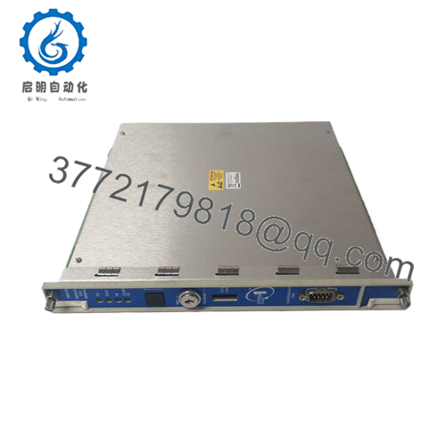
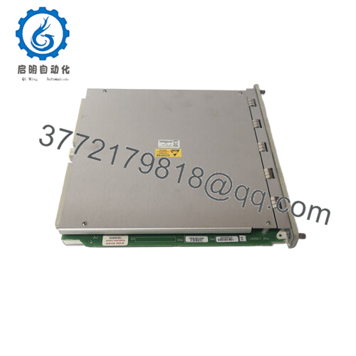
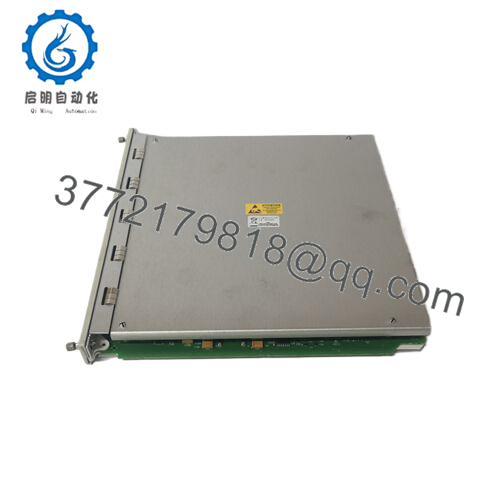
The Bently Nevada 3500/50 136703-01 is a full-height, 2-channel Tachometer I/O module designed to mount directly in the rear of the 3500 chassis, mating inline with the front-facing 3500/50 main monitoring card. This specific assembly features integrated, factory-certified internal intrinsic safety barriers that condition incoming speed pulses directly from rotating machine shafts, compressor gears, or turbine wheels. By reading pulses from proximity probes or magnetic pickups, it routes raw telemetry into the system to calculate rotative speed, direction, acceleration, or zero-speed thresholds while arresting hazardous electrical surges before they enter potentially explosive gas atmospheres.
Stocking the 136703-01 rear module as a New Surplus asset represents a critical capital and engineering risk-mitigation strategy. Because this board houses sensitive intrinsic safety barriers, relying on third-party refurbished alternatives exposes your monitoring network to degraded zener diodes and compromised isolation loops, risking catastrophic validation failure or un-annunciated channel failure. Purchasing an unenergized, factory-sealed surplus unit secures absolute OEM performance limits, shields your plant infrastructure against lengthy vendor delivery delays, and keeps your total cost of ownership optimized.

- 350022M 138607-01
- 3500/50 136703-01
Installation & Configuration Guide
Stage 1: Pre-Installation (Prep & Safety)
- Verify the targeted rear slot geometry matches the corresponding front 3500/50 tachometer monitor card.
- Ensure you have clear clearances and that all machine speed loops are safely bypassed to prevent an erroneous trip signal from downstream logic processors.
- Affix your grounded ESD wrist strap firmly to the structural framework grounding lug on the 3500 sub-rack housing.
Stage 2: Removal
- De-energize the external field sensor lines landing onto the Euro-style terminal strip blocks of the 136703-01 board.
- Label and carefully loosen the wire terminals, pulling the sensor leads away from the card surface.
- Loosen the upper and lower captive mounting hardware anchoring the rear board, then slide the module out vertically along the guide rail paths.
Stage 3: Installation (Clone & Seat)
- Unbox the new surplus 136703-01 module under strict anti-static field conditions. Check that the component matches your original wiring drawings.
- Slide the full-height I/O card smoothly forward along the designated slot guides until the edge pins mesh firmly into the chassis backplane receptacle.
- Lock the assembly by tightening down the captive face screws to preserve ground-plane integrity.
Stage 4: Power-On & Testing
- Re-terminate the field proximity or magnetic pickup sensor leads to the internal block connectors following original configuration specs.
- Power up the 3500 rack slot. Verify the front-facing tachometer monitor reports an OK status illumination indication.
- Initialize the 3500 Rack Configuration package via your station terminal to ensure the hardware barriers are registered, reading normal rpm values on the live status monitor.
Firmware/Software Versions & Upgrade Notes
The 136703-01 Tachometer I/O card operates primarily as a physical field termination layer with integral analog isolation hardware barriers. It does not possess an independent microprogrammable controller chip and does not run standalone field firmware.
However, its physical presence must match configuration setups in your 3500 Rack Configuration software utility. When configuring the slot, you must change your options selection specifically to denote an “I/O Module with Internal Barriers and Internal Terminations.” Setting the software profile mismatching the actual hardware will cause the front-end 3500/50 main processor card to flag an active Configuration Fault, which drops the channel status down into a permanent error state until corrected.
Frequently Asked Questions (FAQ)
What makes the 136703-01 different from standard 3500/50 I/O cards?
The key differentiator is the addition of internal intrinsic safety barriers on the circuit board. While a standard speed input module requires external barrier blocks when routing probes into Class I, Division 1 hazardous process environments, the 136703-01 handles this isolation natively within the 3500 chassis profile, reducing space requirements and terminal junctions.
Can I run magnetic pickups and proximity probes simultaneously on this card?
Yes, the 136703-01 houses two separate speed input channel circuits. Each channel can be assigned and wired independently via configuration profiles to accept either standard negative-voltage proximity probes or self-generating passive magnetic pickups, providing excellent adaptability for complex turbomachinery train layouts.
Is this surplus module safe to deploy in hazardous chemical areas?
Yes, the 136703-01 features integrated barriers engineered to comply with strict hazardous area certifications (such as CSA/NRTL/C and ATEX codes). When installed exactly according to Bently Nevada control drawings, it restricts maximum fault energy transfer to field components located within explosive areas.
What is the failure risk of deploying a refurbished barrier board?
The safety integrity of an internal barrier module relies heavily on zener diodes and resistor paths. Refurbished or repaired boards often carry underlying thermal stress from operational environments, which degrades these components over time and risks premature component failure. This can result in unstable speed tracking or a total loss of intrinsic safety isolation. Utilizing New Surplus preserves original factory reliability baselines.
Does this rear I/O module require an independent warranty package?
Every New Surplus 136703-01 module we ship includes our full 1-year product replacement warranty. This ensures protection against defects and matches standard factory security envelopes for mission-critical machinery monitoring systems.



