
 WhatsApp: +86 16626708626
 Email:
  Phone: +86 16626708626
Description
Key Technical Specifications
| Parameter | Value |
|---|---|
| Manufacturer | Bently Nevada |
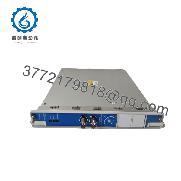
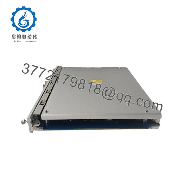
| Product Model | 3500/50M 286566-02 |
| Product Family | 3500 Machinery Protection System |
| Product Type | Tachometer Module |
| Monitoring Channels | 2 Independent Channels |
| Supported Inputs | Proximitor® Probes, Magnetic Pickups |
| Measurement Functions | Shaft Speed, Rotor Acceleration, Reverse Rotation |
| Alarm Functions | Speed Band, Zero Speed, Overspeed Alarm Logic, Reverse Rotation |
| Configuration Software | 3500 Rack Configuration Software |
| Typical Power Consumption | 5.8 W |
| Installation | Standard 3500 Rack Slot |
| Application | Turbine Supervisory Instrumentation (TSI), Machinery Protection |
The 3500/50M accepts two transducer inputs and continuously measures shaft rotational speed, rotor acceleration, and reverse rotation. It compares measured values against programmable alarm limits and can provide conditioned Keyphasor® signals to other monitors within the 3500 rack.
Product Introduction
The Bently Nevada 3500/50M 286566-02 is a dedicated tachometer module for the 3500 Machinery Protection System. It is designed for continuous online monitoring of rotating equipment where accurate speed measurement is essential for machine protection, startup sequencing, and turbine supervisory instrumentation (TSI).
Unlike general-purpose vibration monitors, the 3500/50M focuses on rotational speed measurement. It supports proximity probes and magnetic pickups, provides programmable speed alarms, detects reverse rotation, monitors rotor acceleration, and distributes conditioned Keyphasor® signals throughout the rack without requiring a separate Keyphasor module.
Installation & Configuration Guide
Stage 1 – Pre-Installation Preparation (10 Minutes)
⚠️ Safety First
- Notify operations personnel.
- Lock out and tag out all electrical power.
- Wait at least five minutes before servicing the rack.
- Wear an ESD wrist strap.
Required Tools
- Phillips screwdriver
- Digital multimeter
- ESD wrist strap
- Wire labels
- Smartphone for documenting wiring
Before Removal
- Back up the 3500 rack configuration.
- Record firmware versions.
- Photograph all field wiring and terminal assignments.
Stage 2 – Removing the Existing Module (5 Minutes)
- Remove the rack front cover.
- Label every cable.
- Disconnect field wiring carefully.
- Release the retaining mechanism.
- Pull the module straight out without twisting.
⚠️ Leave the original module available until the replacement has completed commissioning successfully.
Stage 3 – Installing the New Module (10 Minutes)
- Verify the replacement part number is 3500/50M 286566-02.
- Confirm the correct I/O module is installed.
- Insert the module until fully seated.
- Secure the retaining hardware.
- Reconnect all field wiring.
- Verify proximity probe or magnetic pickup polarity.
Installation Checklist
- ✔ Correct model installed
- ✔ Wiring verified
- ✔ I/O module matches application
- ✔ Module fully seated
Stage 4 – Power-On & Commissioning (10 Minutes)
- Restore rack power.
- Confirm normal LED indications.
- Connect using 3500 Rack Configuration Software.
- Verify channel configuration.
- Confirm speed readings.
- Test alarm setpoints.
- Validate Keyphasor® output if used by other monitors.
⚠️ If speed values remain at zero after startup, verify sensor wiring, probe gap, and input type before replacing the module. Communication issues are more commonly caused by configuration or firmware mismatches than by hardware failure.

- 3500/50M 286566-02
- 3500/50M 286566-02
Frequently Asked Questions (FAQ)
Q1. What does the 3500/50M monitor?
It measures shaft rotational speed, rotor acceleration, reverse rotation, and provides programmable speed-based alarms. It is intended for continuous monitoring of rotating machinery.
Q2. Which transducers are supported?
The module accepts signals from:
- Bently Nevada Proximitor® probes
- Magnetic pickup speed sensors
Both input channels operate independently for flexible machine monitoring.
Q3. Is the 3500/50M suitable for overspeed protection?
No. Although it measures shaft speed and generates speed alarms, Baker Hughes specifies that the 3500/50M is not designed as a dedicated overspeed protection system. Separate certified overspeed protection should be used where required by the application.
Q4. Can this module replace a separate Keyphasor module?
In many applications, yes. The 3500/50M can provide conditioned Keyphasor® signals to the rack backplane, eliminating the need for a separate Keyphasor module in compatible system configurations.
Q5. Will replacing the module erase my configuration?
No. The rack configuration is maintained separately. Even so, always export the current configuration before replacing any monitoring module to reduce commissioning time.
Q6. What is the typical application for the 3500/50M?
Typical installations include:
- Steam turbines
- Gas turbines
- Centrifugal compressors
- Turboexpanders
- Large industrial pumps
- Generators
- Turbine Supervisory Instrumentation (TSI) systems
Q7. What does the part number 286566-02 indicate?
286566-02 identifies a specific hardware configuration of the 3500/50M Tachometer Module within the 3500 Series. When ordering a replacement, always verify the complete assembly number, I/O module option, and hazardous-area approval to ensure compatibility with the installed rack.



