
 WhatsApp: +86 16626708626
 Email:
  Phone: +86 16626708626
Description
3. Key Technical Specifications
| Parameter | Value |
|---|---|
| Product Type | Electronic Overspeed Detection Module |
| Series | Bently Nevada 3500 Machinery Protection System |
| Part Number | 133388-01P |
| Module Model | 3500-53 |
| Primary Function | Turbine overspeed monitoring and shutdown protection |
| Voting Architecture | 2-out-of-2 (2oo2) or 2-out-of-3 (2oo3 Recommended) |
| System Requirement | 3500 Rack with Redundant Power Supplies |
| Applicable Standard | API 670 & API 612 Overspeed Protection |
| Operating Temperature | -30 °C to +65 °C |
| Storage Temperature | -40 °C to +85 °C |
| Relative Humidity | Up to 95%, non-condensing |
| Typical Dimensions | 241.3 × 24.4 × 241.8 mm |
| Approximate Weight | 0.82 kg |
| Diagnostics | Built-in self-diagnostics and fault memory |
The suffix “P” identifies a specific hardware revision. Always verify the complete part number and hardware revision before replacement to ensure compatibility with the installed rack and firmware.
4. Product Introduction
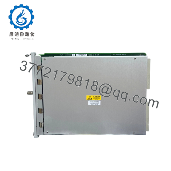
The Bently Nevada 3500-53 133388-01P is an Electronic Overspeed Detection Module designed for the 3500 Machinery Protection System. It continuously monitors turbine and rotating equipment speed, compares measured values with configured trip points, and initiates protective actions before dangerous overspeed conditions can damage critical assets.
Unlike general-purpose speed monitors, the 3500-53 is designed specifically for safety-related overspeed protection. It supports redundant tachometer architectures and voting logic that satisfy API 670 machinery protection requirements for steam turbines, gas turbines, compressors, and other high-speed rotating equipment.

- 3500-53 133388-01P
5. Installation & Configuration Guide
Stage 1 — Pre-Installation Preparation (10 Minutes)
⚠️ Safety First
- Notify operations and maintenance personnel.
- Bring the protected machine to a safe shutdown state.
- Apply Lock-Out/Tag-Out procedures.
- Remove power from the 3500 rack.
- Wait at least 5 minutes before touching internal modules.
Tools Required
- Grounded ESD wrist strap
- PH1 screwdriver
- Fluke 115 multimeter
- Wire labels
- Smartphone for documentation
- 3500 Configuration Software
Data Backup
- Export the complete rack configuration.
- Record overspeed trip settings.
- Document relay assignments.
- Photograph all field wiring.
- Record firmware revisions of every installed monitor.
Stage 2 — Removing the Existing Module (5 Minutes)
- Remove the rack front cover.
- Label every field cable before disconnecting.
- Disconnect the I/O module carefully.
- Release the retaining clips.
- Pull the module straight out without twisting.
Inspect the rack connector for:
- Bent pins
- Dust contamination
- Corrosion
- Loose connectors
⚠️ Keep the removed module until the replacement completes all functional tests successfully.
Stage 3 — Installing the Replacement Module (10 Minutes)
- Connect your ESD wrist strap.
- Confirm the replacement is 3500-53 133388-01P.
- Verify the hardware revision matches site requirements.
- Install the module evenly into the rack.
- Confirm the locking tabs engage fully.
- Reconnect all field wiring.
Self-Checklist
- ☑ Model verified
- ☑ Hardware revision verified
- ☑ Wiring secured
- ☑ Module fully seated
- ☑ Locking tabs engaged
Stage 4 — Power-On & Functional Testing (15 Minutes)
Pre-Power Checks
- Measure the 24 V supply.
- Check for shorts.
- Confirm redundant power supplies are healthy.
Startup Procedure
- Energize the rack.
- Verify module LEDs complete normal startup.
- Connect using 3500 Configuration Software.
- Verify firmware revision.
- Confirm speed inputs are detected.
- Simulate speed inputs if a test bench is available.
- Verify configured alarm and trip points.
- Confirm relay operation.
- Review the event log for faults.
⚠️ Troubleshooting Notes
ERR LED remains ON
- Firmware revision mismatch
- Incorrect hardware revision
- Configuration incompatibility
Speed Not Detected
- Incorrect probe gap
- Damaged Keyphasor® sensor
- Open circuit wiring
- Incorrect sensor polarity
Unexpected Trip
- Incorrect overspeed setpoint
- Voting logic configuration error
- Faulty speed input
Engineer’s Installation Notes
One mistake I’ve watched repeatedly during turbine shutdowns is replacing the overspeed module without documenting the existing trip logic. The hardware installation usually takes less than ten minutes—the recovery from an undocumented configuration can take the rest of the shift.
Another point worth checking is the suffix code. Two modules may both read “3500-53,” yet different hardware revisions can affect compatibility with existing firmware or documentation. Verify the complete ordering code before installation, not just the base model number.
6. Frequently Asked Questions (FAQ)
Q1. Can this module be hot-swapped?
No. Although certain 3500 modules support online replacement, overspeed protection devices should be replaced only during a planned maintenance outage. Removing an active protection module may temporarily reduce the protection integrity of the machinery.
Q2. What equipment typically uses the 3500-53?
It is commonly installed on:
- Steam turbines
- Gas turbines
- Centrifugal compressors
- High-speed pumps
- Turboexpanders
These applications require rapid overspeed detection to protect rotating equipment from catastrophic failure.
Q3. Does the module support redundant protection?
Yes. The 3500-53 supports 2-out-of-2 (2oo2) and 2-out-of-3 (2oo3) voting architectures. Most turbine applications use 2oo3 because it provides higher availability while maintaining safety integrity.
Q4. Is 133388-01P an obsolete model?
The 3500 platform remains widely deployed worldwide, but many hardware revisions are now supplied primarily from new-surplus inventory or specialized automation distributors. Availability varies by hardware suffix and production revision.
Q5. Why is a new surplus module less expensive than buying directly from the OEM?
Many new-surplus units originate from cancelled EPC projects, unused maintenance stock, or excess inventory. A genuine new-surplus module has never been commissioned, but buyers should still request serial-number verification, inspection records, and functional test reports before purchase.
Q6. What quality inspections should a supplier perform before shipment?
A professional inspection process should include:
- OEM serial number verification
- Anti-counterfeit inspection
- Visual inspection for corrosion, scratches, and repair marks
- Functional testing in a genuine 3500 rack
- Simulated overspeed input testing
- 24-hour load testing
- Insulation resistance testing (>10 MΩ)
- Firmware verification
- ESD packaging with QC sign-off
A supplier should also be able to provide inspection photos or test videos upon request. This level of documentation gives far more confidence than simply stating the module is “tested.”



