
 WhatsApp: +86 16626708626
 Email:
  Phone: +86 16626708626
Description
Key Technical Specifications
| Parameter | Value |
|---|---|
| Manufacturer | Bently Nevada |
| Product Model | 3500/54M |
| Product Family | 3500 Machinery Protection System |
| Product Type | Overspeed Detection Monitor |
| Monitoring Channels | Dual redundant speed channels |
| Sensor Compatibility | Proximitor® Probes, Magnetic Speed Pickups |
| Primary Function | Overspeed Protection |
| Alarm Functions | Overspeed Trip, Alert, Diagnostic Monitoring |
| Configuration | 3500 Rack Configuration Software |
| Installation | Standard 3500 Rack Slot |
| System Compliance | Designed for API 670 machinery protection applications |
| Typical Applications | Steam Turbines, Gas Turbines, Compressors, Turboexpanders |
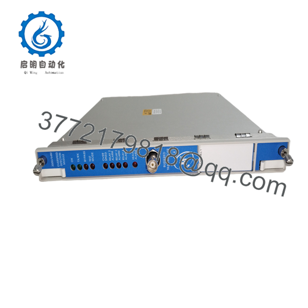
The 3500/54M Overspeed Detection Monitor is designed to provide continuous overspeed protection for rotating equipment. It operates independently of standard speed monitoring modules and is intended for applications where a dedicated overspeed protection function is required.
Product Introduction
The Bently Nevada 3500/54M is a dedicated overspeed detection monitor within the 3500 Machinery Protection System. It continuously acquires shaft speed signals from compatible transducers and compares measured speed against configurable trip setpoints to initiate protective actions before mechanical damage can occur.
Unlike the 3500/50M Tachometer Module, which primarily measures speed and provides operational monitoring, the 3500/54M is intended for independent overspeed protection. It is commonly installed on critical rotating assets where turbine shutdown must occur immediately when an overspeed event is detected.

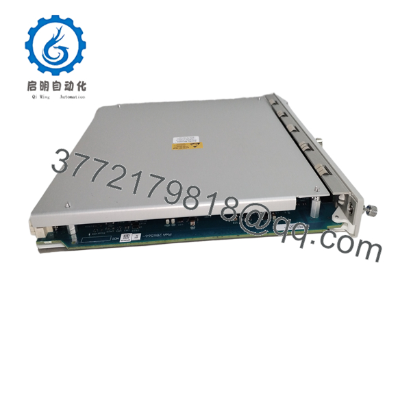
- 3500/54M
- 3500/54M
Installation & Configuration Guide
Stage 1 – Pre-Installation Preparation (10 Minutes)
⚠️ Safety First
- Notify plant operations of the scheduled shutdown.
- Perform Lock-Out/Tag-Out procedures.
- Isolate all control power.
- Wait at least five minutes for stored energy to discharge.
- Wear an ESD wrist strap before handling the module.
Required Tools
- Phillips screwdriver
- Digital multimeter
- ESD wrist strap
- Wire labels
- Smartphone for wiring documentation
Before Removal
- Export the existing 3500 rack configuration.
- Record firmware revisions.
- Photograph all speed sensor wiring and rack connections.
Stage 2 – Remove Existing Module (5 Minutes)
- Remove the rack front cover.
- Label all speed sensor wiring.
- Disconnect field wiring carefully.
- Release the retaining clips.
- Remove the module without twisting.
⚠️ Inspect the rack backplane and connectors before installing the replacement.
Stage 3 – Install the New Module (10 Minutes)
- Verify the replacement is the correct 3500/54M configuration.
- Confirm the matching I/O module is installed.
- Seat the module completely into the rack.
- Secure the retaining hardware.
- Reconnect all sensor wiring according to the original documentation.
- Verify sensor polarity and shielding.
Installation Checklist
- ✔ Correct model verified
- ✔ Wiring matches original installation
- ✔ Module fully seated
- ✔ Grounding confirmed
Stage 4 – Power-On & Functional Testing (10 Minutes)
- Restore rack power.
- Confirm normal module LED status.
- Connect using 3500 Rack Configuration Software.
- Verify overspeed setpoints.
- Simulate speed input where permitted by plant procedures.
- Confirm relay outputs and trip logic operate correctly.
- Record commissioning results.
⚠️ Never perform a live overspeed test on production equipment unless it is part of an approved commissioning procedure. Verify trip logic using simulation whenever possible.
Frequently Asked Questions (FAQ)
Q1. What is the primary purpose of the 3500/54M?
The 3500/54M is designed specifically for independent overspeed detection on critical rotating machinery. It continuously monitors shaft speed and initiates protective actions when configured speed limits are exceeded.
Q2. How is the 3500/54M different from the 3500/50M?
The 3500/50M is primarily a tachometer module for speed measurement, acceleration, and operational monitoring. The 3500/54M is dedicated to overspeed protection and is intended to provide an independent shutdown function for critical machinery.
Q3. Which machines typically use this monitor?
Typical applications include:
- Steam turbines
- Gas turbines
- Turboexpanders
- Centrifugal compressors
- High-speed generators
- Critical rotating equipment requiring independent overspeed protection
Q4. Can the module be replaced while the rack is energized?
No. Bently Nevada recommends removing power before replacing monitor modules to avoid communication faults, configuration corruption, or possible backplane damage.
Q5. Does replacing the module erase configuration settings?
No. Configuration is maintained within the 3500 system database. However, always back up the rack configuration before maintenance to simplify commissioning.
Q6. Which speed sensors are supported?
Depending on the selected I/O module, the 3500/54M supports compatible Proximitor® proximity probes and magnetic pickup speed sensors used for turbine speed measurement.
Q7. Is the 3500/54M suitable for API 670 machinery protection systems?
Yes. The 3500 Machinery Protection System, including the 3500/54M Overspeed Detection Monitor, is designed for applications requiring compliance with API 670 machinery protection practices used throughout the power generation, oil and gas, and process industries.



