

 WhatsApp: +86 16626708626
 Email:
  Phone: +86 16626708626
Description
Key Technical Specifications
| Parameter | Value |
| Channels | 6 independent, non-isolated channels |
| Input Signal Types | 4 to 20 mA, +1 to +5 Vdc, 0 to +10 Vdc, −10 to +10 Vdc |
| Termination Style | Internal Terminations (Integrated Euro-style terminal blocks) |
| Input Impedance | 250 Ω for current inputs, >1 MΩ for voltage inputs |
| Accuracy | ±0.33% of full-scale span over operating range |
| Power Consumption | 5.0 W typical |
| Operating Temperature | −30 to +65 °C (−22 to +150 °F) |
| Storage Temperature | −40 to +85 °C (−40 to +185 °F) |
| Resolution | 16-bit analog-to-digital conversion |
Product Introduction & Supply Chain Strategy
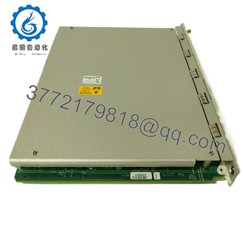
The Bently Nevada 3500/61 series, utilizing the 163179-02 internal termination I/O module, is a six-channel instrument designed to log, process, and protect against out-of-bounds static parameters. While vibration monitors track dynamic motion, the 3500/61 processes slow-moving variables such as lube oil pressure, casing temperature, cooling water flow, and suction pressure. By centralizing these process parameters within the main 3500 machinery protection rack, the system can deploy complex interlock logic, such as inhibiting a machine start if lube oil pressure remains below a critical safety threshold.
From an inventory and maintenance cycle standpoint, maintaining a New Surplus 163179-02 card on-site acts as an essential operational insurance policy. These I/O modules are directly connected to field loops that are vulnerable to external electrical noise, grounding faults, or lightning surges. A single channel failure can cause false trip signals, leading to an unplanned plant outage that triggers significant revenue losses. Sourcing this specific legacy part as a factory-sealed New Surplus item ensures perfect OEM structural integrity and zero degradation of passive timing components. This eliminates the Total Cost of Ownership (TCO) vulnerabilities associated with refurbished or used parts, which often manifest as intermittent calibration drift or trace degradation.

- 163179-02
Installation & Configuration Guide
Stage 1: Pre-Installation (Prep & Safety)
- Ensure the specific channel assignments on the corresponding front monitor module are bypassed or put into a safe manual override mode within the DCS/PLC.
- Fasten a grounded, static-dissipative wrist strap to your arm and attach the ground clip to the rack chassis framework.
- Access the 3500 Configuration Software to upload and verify the current operational profile parameters for the 3500/61 slot.
- Mark and photograph all active analog wiring lines attached to the 163179-02 internal screw terminals.
Stage 2: Removal
- De-energize the external loop power supply if the 4–20 mA loops are powered externally.
- Unscrew the field terminal wires from the internal terminal blocks or pull out the pluggable block assembly if applicable.
- Loosen the upper and lower captive screws on the faceplate of the 163179-02 I/O module using a flat-head screwdriver.
- Pull the module handles straight out to detach the board from the backplane connectors, sliding it evenly out of the card guides.
Stage 3: Installation (Clone & Seat)
- Extract the new surplus 163179-02 module from its factory sealed ESD protection packaging.
- Confirm that any on-board jumper links (such as those choosing between current or voltage tracking modes) are arranged to match the original broken unit.
- Insert the card into the rear slots of the 3500 chassis. Slide the board forward until the male pin blocks link with the mainframe backplane interface.
- Tighten the faceplate captive screws to lock the module frame down securely.
Stage 4: Power-On & Testing
- Re-terminate all analog field lines back onto the corresponding screw ports based on your wiring chart.
- Energize the loop circuitry and check for proper supply voltages at the terminals.
- Observe the front monitor panel lamps; the system status light must display a solid green color, indicating successful initialization.
- Use the 3500 configuration utility to monitor the live 4–20 mA or voltage loops, ensuring the converted software engineering units correspond to the true physical field levels.
Firmware/Software Versions & Upgrade Notes
The 163179-02 I/O board communicates directly with the front-mounted 3500/61 Process Monitor main processing module. To ensure accurate configuration downloads, the firmware version of the front monitor card must be fully aligned with the hardware layout of the rear I/O assembly.
If the replacement 163179-02 contains a newer hardware revision layer, older legacy monitor firmware may flag an “I/O Module Mismatch” error code. Always examine the firmware levels via the 3500 Configuration tool before bringing the machine loops back online. Never clear or update system firmware parameters on an active rack; flash procedures must be performed while the process line is down to eliminate the risk of corrupting the non-volatile memory sector.
Frequently Asked Questions (FAQ)
What is the relationship between the 3500/61 designation and the 163179-02 part number?
The 3500/61 describes the entire multi-channel Process Monitor system within the Bently Nevada catalog. The number 167179-02 identifies the specific rear-mounted Input/Output (I/O) module circuit board featuring internal terminations. To replace a broken rear card, you must match the 163179-02 model code exactly.
Why choose a New Surplus 163179-02 module instead of a lower-cost refurbished alternative?
Refurbished analog processing boards present a hidden operational risk for critical infrastructure. Passive components like resistors and capacitors undergo thermal stress during years of continuous field placement, which can result in calibration errors, signal drift, or unexpected channel failure. A single false trip caused by an uncalibrated refurbished channel can cost tens of thousands of dollars in emergency downtime, completely offsetting any initial savings.
Does the 163179-02 module provide internal loop power for 4–20 mA transmitters?
Yes, the 3500/61 monitor setup can deliver +24 Vdc loop power to run standard external 2-wire process transmitters via the I/O terminal connections. It can also be configured to accept self-powered or isolated 4-wire current signals by adjusting the on-board channel layout settings.
What does “Internal Terminations” mean for this specific card layout?
The internal termination configuration means that field signal wires connect directly to the Euro-style screw terminal strips built onto the face of the 163179-02 module itself. This setup removes the need for external termination blocks and multi-conductor interface cables, saving valuable cabinet footprint space.
Will changing out this rear I/O block wipe the programmed channel setpoints?
No. The alarm levels, scale limits, and channel voting matrices are safely stored in the non-volatile EEPROM memory of the front-mounted 3500/61 processor module or the main Rack Interface Module (RIM). The rear I/O card handles physical routing and signal conditioning. However, you must verify that all onboard configuration jumpers on the new surplus card are matched perfectly to the original unit before power-on.


