
 WhatsApp: +86 16626708626
 Email:
  Phone: +86 16626708626
Description
Key Technical Specifications
| Parameter | Value |
|---|---|
| Manufacturer | Bently Nevada |
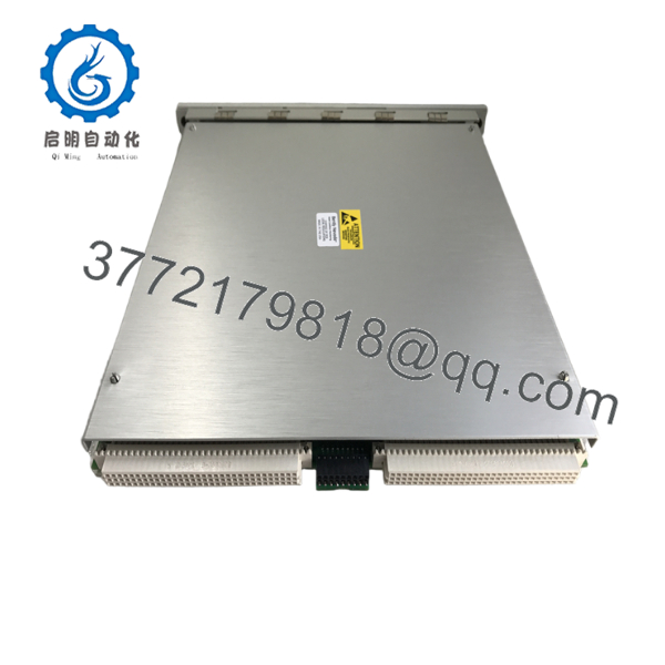
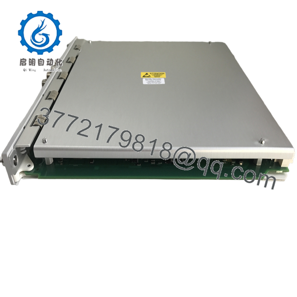
| Product Model | 3500/70-01-01 |
| Product Family | 3500 Machinery Protection System |
| Product Type | 4-Channel Recip Impulse Velocity Monitor |
| Monitoring Channels | 4 Independent Channels |
| Supported Sensors | Bently Nevada 330400, 330425, Velomitor® CT seismic transducers |
| Measurement Functions | Impulse Acceleration, Acceleration 2, Recip Velocity, Low Frequency Recip Velocity |
| Alarm Functions | User-configurable Alert and Danger alarms |
| Configuration | 3500 Rack Configuration Software |
| Rack Installation | Standard 3500 Rack Slot |
| Application Standard | Designed for reciprocating machinery monitoring consistent with API 618 applications |
| Typical Industries | Oil & Gas, Petrochemical, LNG, Pipeline Compression |
The 3500/70-01-01 is a dedicated monitor for reciprocating compressors. It conditions acceleration and velocity signals from seismic transducers, calculates machinery condition variables, and compares them with programmable alarm limits for continuous protection.
Product Introduction
The Bently Nevada 3500/70-01-01 Recip Impulse Velocity Monitor is engineered specifically for reciprocating compressors. Unlike monitors intended for turbines or centrifugal machinery, this module analyzes vibration characteristics unique to reciprocating equipment, helping maintenance personnel identify mechanical faults before they result in unplanned shutdowns.
The monitor accepts vibration signals from approved seismic transducers, performs signal conditioning, and generates measurements including impulse acceleration, acceleration, reciprocating velocity, and low-frequency reciprocating velocity. These measurements support predictive maintenance programs and machinery protection systems throughout compressor installations.

- 3500/70-01-01
- 3500/70-01-01
Installation & Configuration Guide
Stage 1 – Pre-Installation Preparation (10 Minutes)
⚠️ Safety First
- Notify operations before removing the monitor.
- Perform Lock-Out/Tag-Out procedures.
- Remove power from the 3500 rack.
- Wait at least five minutes before handling electronics.
- Wear a grounded ESD wrist strap.
Required Tools
- Phillips screwdriver
- Digital multimeter
- ESD wrist strap
- Wire labels
- Smartphone for documenting wiring
Before Removal
- Save the existing 3500 rack configuration.
- Record firmware revisions.
- Photograph all transducer wiring and rack connections.
Stage 2 – Removing the Existing Module (5 Minutes)
- Remove the rack front cover.
- Label all field cables.
- Disconnect sensor wiring.
- Release the retaining latch.
- Remove the module straight out to protect the backplane connectors.
⚠️ Do not discard the existing module until commissioning of the replacement has been completed successfully.
Stage 3 – Installing the New Module (10 Minutes)
- Verify the replacement part number is 3500/70-01-01.
- Confirm the matching I/O module is installed.
- Insert the monitor fully into the rack.
- Tighten retaining hardware.
- Reconnect all seismic transducer wiring.
- Verify cable shielding and grounding.
Installation Checklist
- ✔ Model number verified
- ✔ Wiring restored correctly
- ✔ Module fully seated
- ✔ Grounding confirmed
Stage 4 – Power-On & Commissioning (10 Minutes)
- Restore rack power.
- Verify the module LEDs indicate normal operation.
- Connect using 3500 Rack Configuration Software.
- Configure the required measurement variables.
- Verify sensor inputs and channel scaling.
- Test Alert and Danger alarm functions.
- Record commissioning data.
⚠️ If channel values remain unstable, inspect the seismic transducer installation and cable shielding before replacing the monitor. Many apparent module faults are actually caused by sensor mounting or wiring issues.
Frequently Asked Questions (FAQ)
Q1. What is the primary purpose of the 3500/70-01-01?
The 3500/70 monitors vibration characteristics specific to reciprocating compressors. It measures impulse acceleration, acceleration, reciprocating velocity, and low-frequency reciprocating velocity to help detect developing mechanical problems.
Q2. Which transducers are supported?
Compatible sensors include:
- Bently Nevada 330400
- Bently Nevada 330425
- Velomitor® CT seismic transducers
These sensors provide the acceleration and velocity signals required by the monitor.
Q3. Is this monitor intended for steam turbines?
No. The 3500/70 is optimized for reciprocating compressors. Steam turbines and centrifugal compressors typically use other 3500 Series monitors, such as the 3500/40M, 3500/42M, or 3500/45, depending on the required measurements.
Q4. Can the module be hot-swapped?
No. The recommended maintenance procedure is to de-energize the rack before replacing monitor modules to avoid communication errors or possible backplane damage.
Q5. Will replacing the module erase my configuration?
No. The rack configuration is stored separately from the monitor hardware. Even so, always export the configuration before maintenance to simplify commissioning.
Q6. What industries commonly install the 3500/70?
Typical applications include:
- Natural gas compression stations
- Petrochemical plants
- LNG facilities
- Refinery reciprocating compressors
- Pipeline compressor stations
- Industrial process gas compressors
Q7. Why is a dedicated reciprocating monitor required?
Reciprocating compressors generate vibration patterns that differ significantly from rotating equipment such as turbines or centrifugal compressors. The 3500/70 uses measurement algorithms specifically developed for reciprocating machinery, providing earlier detection of valve problems, crosshead wear, rod looseness, and impact-related faults than general-purpose vibration monitors.



