
 WhatsApp: +86 16626708626
 Email:
  Phone: +86 16626708626
Description
3. Key Technical Specifications
| Parameter | Specification Value |
|---|---|
| Channel Count | 4 full-measurement channels per module |
| Input Sensors | Accelerometers, Velomitors, Proximitor Sensors |
| Signal Processing Modes | Reciprocating Velocity, Acceleration, Impulse/Impact, Rod Drop |
| A/D Conversion | 24-bit high-resolution resolution |
| Frequency Range | Variable from 1.0 Hz up to 5 kHz depending on selected configuration |
| Front Panel Interfaces | 4 dedicated coaxial BNC ports for raw signal analysis |
| System Compatibility | Integrates with standard 3500 rack and 3500/22M TDI modules |
| Power Draw | 7.5 Watts typical backplane draw |
| Isolating Outputs | 4 to 20 mA analog outputs available via corresponding I/O modules |
4. Product Introduction & Supply Chain Strategy
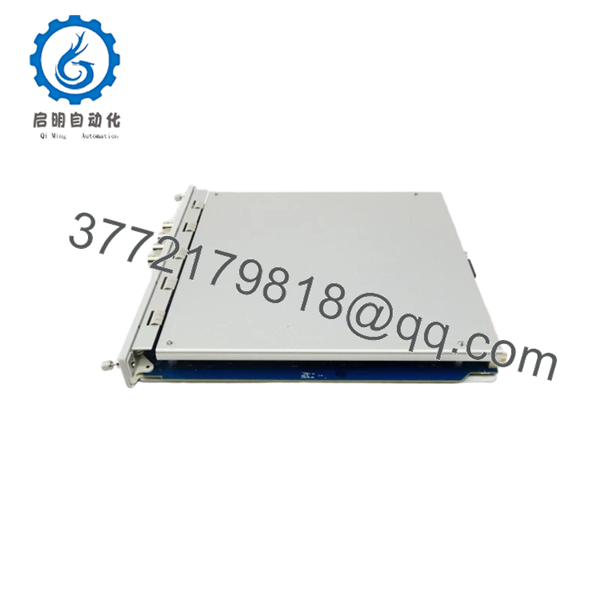
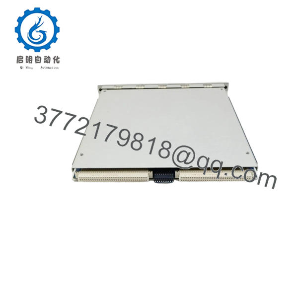
The Bently Nevada 3500-70 is a 4-channel processing monitor purpose-built to track mechanical wear inside reciprocating compressors. Unlike standard continuous vibration modules, the 3500-70M isolates impulsive, short-duration kinetic impacts—such as loose piston rods, liquid slugging, or worn valve components—and calculates cross-head acceleration and rod drop variations to alert operators before fatal structural breakdowns happen.
Acquiring this module as a New Surplus unit is a vital step for mitigating total lifecycle costs across high-availability plants. Reciprocating compressors operate under extreme cyclical stresses, making the monitoring loops sensitive to minor signal skewing. Refurbished internal circuits cannot guarantee the precision microsecond parsing required for intermittent impact tracking, introducing the danger of false trips or unmitigated mechanical impact faults. Deploying a certified New Surplus module eliminates these secondary failure points, guaranteeing OEM-level timing accuracy while shielding the facility budget against factory backlogs.
5. Installation & Configuration Guide
1Pre-Installation Prep & SafetyEstimated time: 10 min1.Pre-Installation Prep & Safety:Estimated time: 10 min.
Obtain a complete configuration snapshot via the 3500 Rack Configuration software. Strap on a grounded ESD-safe wristband prior to opening the static shielding bag. Inhibit the trip relays assigned to the target slot to safeguard the compressor from tripping while the loop is open.
2Module RemovalEstimated time: 5 min2.Module Removal:Estimated time: 5 min.
Loosen the structural retaining hardware located on the upper and lower borders of the existing 3500-70M front panel. Pivot the integrated extraction tabs outward to cleanly separate the module from the backplane assembly, then draw the card smoothly down the rack guide channels.
3Jumper Setup & SeatingEstimated time: 10 min3.Jumper Setup & Seating:Estimated time: 10 min.
Examine the hardware jumpers on the new PWA board to confirm they match the transducer inputs specified in your engineering plan (e.g., verifying power requirements for standard accelerometers vs. proximity probes). Insert the module firmly into place along the chassis tracks, then torque the retention screws.
4Power Restoration & MappingEstimated time: 15 min4.Power Restoration & Mapping:Estimated time: 15 min.
Re-energize the rack assembly and observe the self-test sequence. The “OK” status lamp should glow green. Open your 3500 system software to bind the specific reciprocating profile (e.g., Impact or Rod Drop scaling factors) and download the file to the module’s non-volatile memory.

- 3500-70
- 3500-70
6. Firmware/Software Versions & Upgrade Notes
The 3500-70M requires matched firmware revisions to handshake properly with the 3500/25 Enhanced Keyphasor and 3500/22M TDI modules, especially when performing rod drop calculations tied to specific rotational positions. Mismatched firmware can cause time-stamp slippage across the internal backplane bus, causing the system to miscalculate peak impact intervals.
When placing a newer revision PWA component into an existing legacy system, evaluate the complete rack firmware baseline first. If an upgrade is required to maintain interface consistency, apply the modification using a dedicated, hardwired configuration port rather than a network connection to prevent packet loss during the EEPROM burning sequence.
7. Frequently Asked Questions (FAQ)
What differentiates the 3500-70M from a standard vibration card like the 3500-42M? Standard cards focus on continuous, sinusoidal movement typically found in centrifugal bearings. The 3500-70M is optimized for the non-continuous, mechanical shocks typical of reciprocating machinery, capturing peak acceleration bursts during valve closures and checking rod position relative to specific stroke positions.
Why should I buy a New Surplus unit rather than a lower-cost repaired module? Repreciprocating impact detection relies heavily on fast, un-degraded analog processing chips. Refurbished options may utilize alternative components or possess aged capacitive filters that introduce signal damping, leading to missed valve defect indicators. New Surplus units guarantee original factory tolerances, avoiding costly mechanical failures.
Can this module handle both Rod Drop and Impact monitoring profiles simultaneously? Yes, but configuration options are determined on a per-pair or per-channel basis within the configuration utility. You can structure channels 1 and 2 to analyze crosshead impact while dedicating channels 3 and 4 to measure physical rod drop, provided the correct input sensors are wired to the matching I/O block.
Does the module need an independent timing signal for rod position tracking? For standard impact and velocity monitoring, individual sensors operate autonomously. However, if you configure the card for multi-segment Rod Drop or Crank-Angle tracking, the 3500-70M must read a phase reference input supplied by a 3500/25 Keyphasor card residing within the same rack.
What warranty coverage applies to this certified New Surplus asset? Every New Surplus Bently Nevada 3500-70M module we ship includes our direct 1-year industrial replacement warranty. If any channel processing or backplane addressing deviations manifest under normal plant usage, we will issue a direct component replacement.



