
 WhatsApp: +86 16626708626
 Email:
  Phone: +86 16626708626
Description
Key Technical Specifications
| Parameter | Value |
|---|---|
| Manufacturer | Bently Nevada |
| Model Number | 350015-05-05-R0 |
| Product Type | 3300 XL Proximitor Sensor |
| System Series | 3300 XL 8 mm Proximity Transducer System |
| Measurement Principle | Eddy-current non-contact displacement measurement |
| Probe Compatibility | 3300 XL 8 mm Proximity Probe |
| Extension Cable Compatibility | 3300 XL Extension Cable |
| Supply Voltage | -17.5 V DC to -26 V DC typical |
| Current Consumption | Approximately 12 mA maximum |
| Output Signal | Voltage proportional to shaft displacement |
| Typical Sensitivity | 100 mV/mil (3.94 V/mm) system output |
| Operating Temperature | -52 °C to +100 °C |
| Storage Temperature | -52 °C to +105 °C |
| Mounting | DIN rail or panel mounting |
| Applications | Radial vibration, shaft position, Keyphasor reference measurement |
The 3300 XL 8 mm Proximity Transducer System uses a complete measurement chain consisting of the probe, extension cable, and Proximitor Sensor. The system provides an output voltage proportional to the distance between the probe tip and the conductive shaft surface, allowing measurement of both dynamic vibration and static shaft position.
Engineering Note:
The suffix R0 identifies a specific ordering configuration. Confirm the full OEM ordering code, hazardous-area approval requirements, and existing probe/cable combination before installation. Similar 350015 part numbers may not always be interchangeable.
Product Introduction
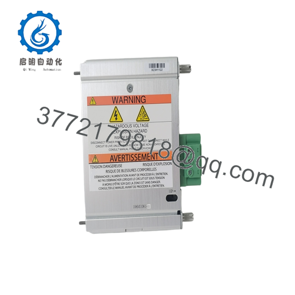
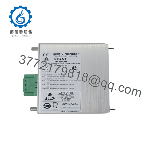
The Bently Nevada 350015-05-05-R0 is a 3300 XL 8 mm Proximitor Sensor designed for rotating machinery condition monitoring applications. It receives signals from a compatible 3300 XL proximity probe and converts the eddy-current measurement into a proportional output signal used by vibration monitors, turbine protection systems, and plant control interfaces.
This sensor is commonly used in existing Bently Nevada 3300 XL installations where plants need to maintain existing monitoring channels without redesigning the complete protection system. Before replacement, verify probe type, cable length, supply polarity, and monitor input configuration.

- 350015-05-05-R0
- 350015-05-05-R0
Installation & Configuration Guide
Stage 1: Pre-Installation Preparation (Estimated Time: 10 Minutes)
⚠️ Safety First
Before replacing the Bently Nevada 350015-05-05-R0:
- Notify operations personnel about the planned maintenance activity.
- Confirm equipment shutdown requirements.
- Apply lockout/tagout (LOTO) procedures.
- Isolate the instrumentation power supply.
- Wait at least 5 minutes for stored electrical energy discharge.
Tools Required
- ESD wrist strap
- PH1 screwdriver
- Digital multimeter
- Wire labels
- Smartphone/camera
- Electrical drawings
- Bently Nevada installation documentation
Data Backup
Before disconnecting:
- Photograph the existing terminal wiring.
- Record the installed sensor model number.
- Record probe and extension cable part numbers.
- Document monitor channel settings.
- Record vibration alarm thresholds.
- Photograph mounting position.
⚠️ Take wiring photos before removing terminals. This avoids unnecessary troubleshooting during startup.
Stage 2: Removing the Old Module (Estimated Time: 10 Minutes)
- Remove the protective cover or enclosure access panel.
- Label all connected wires.
- Disconnect power wiring.
- Disconnect probe input wiring.
- Disconnect output signal wiring.
- Release mounting clips.
- Remove the sensor carefully.
Inspect:
- Terminal condition
- Cable insulation
- Shield termination
- Mounting hardware
- Moisture or contamination
⚠️ Do not discard the old unit immediately. Keep it available until the replacement has completed functional testing.
Stage 3: Installing the New Module (Estimated Time: 10 Minutes)
Step 1: ESD Preparation
- Wear a grounded wrist strap.
- Place the module on an ESD-safe surface.
- Avoid touching electrical contacts.
Step 2: Verify Replacement Compatibility
Confirm:
- Model: 350015-05-05-R0
- System: 3300 XL 8 mm
- Probe compatibility
- Extension cable length
- Supply voltage requirements
Step 3: Wiring Transfer
Reconnect:
- Power supply terminals.
- Probe input connection.
- Signal output wiring.
- Shield grounding connection.
⚠️ Do not wire by memory. A wrong polarity connection can damage instrumentation electronics or create incorrect vibration readings.
Step 4: Mechanical Installation
- Mount the sensor securely.
- Verify DIN rail or panel mounting.
- Tighten terminals correctly.
- Confirm wiring identification.
Checklist:
- Correct model installed
- Probe verified
- Cable verified
- Supply polarity checked
- Shield connection restored
Stage 4: Power-On & Testing (Estimated Time: 20–30 Minutes)
Pre-Power Check
Using a multimeter:
- Verify supply voltage.
- Confirm correct polarity.
- Check for accidental shorts.
- Verify grounding continuity.
Power-On Steps
- Energize the instrumentation circuit.
- Verify sensor output voltage.
- Check vibration monitor input.
- Compare readings with previous values.
- Confirm DCS/PLC scaling.
- Perform controlled equipment testing.
⚠️ Troubleshooting Notes
No output signal:
Check:
- Sensor supply voltage
- Probe connection
- Extension cable continuity
- Monitor input configuration
Incorrect vibration reading:
Check:
- Probe gap voltage
- Probe/cable combination
- Calibration assumptions
- Signal scaling
Unexpected alarm after replacement:
Do not immediately change alarm limits. Verify the complete measurement chain first.
Frequently Asked Questions (FAQ)
Q1: Can the Bently Nevada 350015-05-05-R0 be hot-swapped?
No. Power should be removed before replacement. The Proximitor Sensor is part of a machinery protection measurement chain, and live wiring changes can create false signals or damage instrumentation circuits.
Q2: What system does the 350015-05-05-R0 belong to?
It belongs to the Bently Nevada 3300 XL 8 mm Proximity Transducer System. The complete system normally includes the 3300 XL 8 mm probe, extension cable, and Proximitor Sensor.
Q3: Is the 350015-05-05-R0 obsolete?
The 3300 XL family remains installed in many industrial plants. Availability depends on current inventory and lifecycle status. Plants with large installed bases often continue using these parts because replacing the entire vibration monitoring architecture requires engineering effort and downtime planning.
Q4: Will replacing this module erase PLC or DCS programming?
No. The 350015-05-05-R0 does not contain PLC logic or DCS application programs. However, the connected vibration monitoring system may contain channel scaling, alarm limits, and configuration values that should be verified after replacement.
Q5: Is this unit new original or refurbished?
Industrial automation suppliers usually classify inventory as:
- New Original / New Surplus: unused equipment stored in inventory.
- Refurbished (tested): inspected and function-tested equipment.
Request serial number photos, inspection records, and functional test reports before purchase.
Q6: What should be checked before ordering a replacement?
Verify:
- Exact part number: 350015-05-05-R0
- Existing probe model.
- Extension cable length.
- Monitor channel compatibility.
- Hazardous-area certification requirements.
- Required mounting arrangement.
Q7: What quality testing should be completed before shipment?
A professional inspection process should include:
- Inbound inspection and serial number traceability.
- Visual inspection for corrosion, scratches, and rework marks.
- Functional testing on a compatible Bently Nevada 3300 XL test setup.
- Supply voltage verification.
- Signal output verification.
- Final QC documentation.
Test photos and inspection records should be available upon request.



