
 WhatsApp: +86 16626708626
 Email:
  Phone: +86 16626708626
Description
Key Technical Specifications
| Parameter | Specification |
|---|---|
| Manufacturer | Bently Nevada |
| Model | 350050-01-00 |
| System Designation | 3500/50 |
| Product Type | 2-Channel Tachometer Module |
| System | 3500 Machinery Protection System |
| Number of Channels | 2 |
| Input Sources | Eddy-current proximity probes or magnetic pickups |
| Input Signal Range | +10.0 V to -24.0 V |
| Standard Input Impedance | 20 kΩ |
| TMR Input Impedance | 40 kΩ |
| Internal Barrier Input Impedance | 7.15 kΩ |
| Measurement Functions | Shaft speed, rotor acceleration, rotor direction |
| Alarm Setpoints | User programmable |
| Power Consumption | 5.8 W typical |
| Module Dimensions | 241.3 × 24.4 × 241.8 mm |
| Approx. Weight | 0.82 kg |
| Agency Approval Option | None |
| Typical Application | Machinery speed and overspeed-related monitoring |
The 350050-01-00 is identified in current supplier documentation as the Bently Nevada 3500/50 Tachometer Module. The module accepts up to two transducer signals from proximity probes or magnetic pickups and uses those signals to determine shaft speed, rotor acceleration, or rotor direction.
The 3500/50 module compares measured values against user-programmed alarm setpoints and communicates its status through the 3500 rack. The -00 configuration is listed as having no agency approval option.
Product Introduction
The Bently Nevada 350050-01-00, also designated 3500/50, is a two-channel tachometer module for the 3500 Machinery Protection System. It accepts signals from compatible proximity probes or magnetic pickups and determines shaft rotational speed, rotor acceleration, or rotor direction for machinery monitoring and protection applications.
This configuration is useful when a 3500 rack needs hardwired speed information for alarm logic, machinery monitoring, or associated protection functions. The module supports programmable alarm setpoints and provides front-panel status indications for operating condition, rack communication, and bypass status.
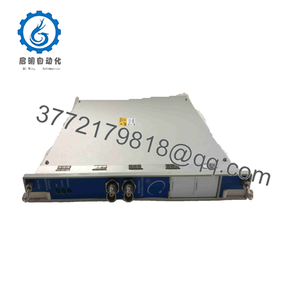
350050-01-00
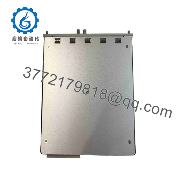
350050-01-00
Installation & Configuration Guide
Stage 1: Pre-Installation Preparation
Estimated time: 15–20 minutes
- Confirm the exact replacement marking: 350050-01-00.
- Verify that the existing rack uses a compatible 3500/50 Tachometer Module configuration.
- Record the existing module’s full part number, revision, and serial number.
- Document which channel is connected to each speed pickup or proximity probe.
- Record the existing tachometer configuration and alarm setpoints using the applicable 3500 configuration software.
- Photograph the rear I/O wiring before removal.
- Prepare an ESD strap, screwdriver, multimeter, wire labels, and the applicable Bently Nevada documentation.
- Notify operations and place the monitored machinery in the approved maintenance state.
- Apply LOTO where required.
⚠️ Do not assume Channel 1 and Channel 2 perform identical functions at the plant. The actual channel assignment and alarm logic must be documented before replacement.
Stage 2: Removing the Old Module
Estimated time: 10–15 minutes
- Confirm the machinery and protection system are in the approved maintenance state.
- Verify whether the rack has redundant power and whether module removal affects the active protection arrangement.
- Identify and label both tachometer input circuits.
- Disconnect the associated I/O wiring carefully.
- Release the module retaining hardware.
- Pull the module straight out of the rack.
- Inspect the backplane connector and module edge connector.
- Check the external probe or magnetic-pickup wiring for loose terminals, shield damage, or corrosion.
- Retain the old module until the replacement has passed commissioning.
⚠️ Do not pull on the transducer cable itself. A damaged coaxial or pickup cable can create an apparent tachometer-module fault after the replacement.
Stage 3: Installing the New 350050-01-00
Estimated time: 10–15 minutes
- Verify that the replacement is 350050-01-00.
- Compare the front-panel markings with the removed module.
- Inspect the connector and rack slot for contamination or mechanical damage.
- Align the module with the correct 3500 rack position.
- Insert the module carefully into the backplane connector.
- Secure the retaining hardware.
- Reconnect Channel 1 and Channel 2 wiring according to the recorded configuration.
- Verify signal polarity and shielding.
- Check that no pickup wire has been moved between channels.
Self-check:
- Correct 3500/50 module
- Correct rack position
- Channel 1 wiring verified
- Channel 2 wiring verified
- Shielding checked
- Alarm configuration backed up
Stage 4: Power-On & Testing
Estimated time: 20–30 minutes
- Perform a visual inspection before energizing the rack.
- Check the applicable input circuit for unintended shorts.
- Restore rack power according to the approved maintenance procedure.
- Observe the front-panel OK LED.
- Check the TX/RX indication for rack communication.
- Confirm the module is recognized by the 3500 configuration software.
- Verify the programmed speed range and alarm setpoints.
- Confirm the correct transducer signal appears on Channel 1 and Channel 2.
- Start the machine according to the approved operating procedure.
- Compare measured speed against an independent reference where available.
- Verify rotor acceleration or direction functions if configured.
- Test the applicable alarm outputs using an approved commissioning method.
- Document the final readings and configuration.
The 3500/50 front panel includes OK, TX/RX, and Bypass status indicators. A normal module startup should be evaluated together with the rack configuration and actual transducer signal rather than by LED status alone.
⚠️ Do not use a tachometer alarm test as an uncontrolled overspeed test. For machinery connected to a shutdown circuit, use the site’s approved simulation or functional-test procedure.
Frequently Asked Questions
Q1. What is Bently Nevada 350050-01-00?
It is a Bently Nevada 3500/50 two-channel Tachometer Module used in the 3500 Machinery Protection System. It processes signals from compatible proximity probes or magnetic pickups to determine shaft speed, rotor acceleration, or rotor direction.
Q2. How many tachometer inputs does the 3500/50 provide?
The module provides two input channels. Each channel can accept a compatible signal from a proximity probe or magnetic pickup, subject to the specified input characteristics and the installed I/O configuration.
Q3. What is the input voltage range?
Published specifications for the 3500/50 identify an input signal range of approximately +10.0 V to -24.0 V. Input impedance varies according to the module configuration, including standard, TMR, and internal-barrier arrangements.
Q4. Can 350050-01-00 replace another 3500/50 module?
Not automatically. The complete part number and I/O configuration must be checked. For example, 3500/50 variants can differ in I/O termination and agency-approval configuration. Verify the existing module, rear I/O arrangement, and plant certification requirements before substitution.
Q5. Does the 350050-01-00 require programming?
The module uses the 3500 System Configuration Software for its operating configuration, including applicable measurement and alarm parameters. A replacement should therefore be treated as a configuration-controlled component, not simply a hardware swap.
Q6. Can the module be hot-swapped?
Do not assume that it can be removed under power. The tachometer module may be part of active machinery-speed or shutdown logic. Follow the applicable Bently Nevada 3500 maintenance procedure and plant protection procedure before removing the module.
Q7. What should I verify before ordering 350050-01-00?
Verify the exact 350050-01-00 part number, module revision, I/O configuration, transducer type, channel assignments, alarm setpoints, rack configuration, and required agency approvals. Current listings also show other 3500/50 configurations, including 3500/50-01-00-01, so the final suffix should not be omitted when ordering.



