
 WhatsApp: +86 16626708626
 Email:
  Phone: +86 16626708626
Description
Key Technical Specifications
- Parameter: Model — 3701/55
- Parameter: Part Number — 289761-01
- Parameter: Manufacturer — Bently Nevada, a Baker Hughes business
- Parameter: Product Type — ADAPT ESD Terminal Base Assembly
- Parameter: System — 3701/55 ADAPT ESD Emergency Shutdown Device
- Parameter: Primary Function — Terminal and mechanical interface for ADAPT ESD modules
- Parameter: Compatible CPU Module — 323174-01 ADAPT ESD CPU Module
- Parameter: Compatible Relay Modules — 323073-01 / 323073-02
- Parameter: Mounting Orientation — Vertical
- Parameter: Enclosure Depth — Minimum 9 in. according to the 3701/55 installation drawing
- Parameter: Installation Requirement — Power supply terminal exits horizontally for heat dissipation
- Parameter: Reference Datasheet — Bently Nevada 100M8833, 3701/55 ADAPT ESD
Important identification note: Some reseller listings incorrectly describe 289761-01 as a seismic velocity transducer or as the complete ESD monitor. Bently Nevada’s own published accessory list identifies 289761-01 as the ADAPT ESD Terminal Base Assembly. Verify the physical nameplate and ordering code before replacement.
Product Introduction
The Bently Nevada 3701/55 289761-01 is the terminal base assembly used with the 3701/55 ADAPT ESD emergency shutdown system. It provides the physical and electrical interface for the associated ADAPT ESD modules, including the 323174-01 CPU and compatible relay output modules.
This part matters during replacement because the terminal base is part of the installed system architecture, not simply a generic mounting plate. The Bently Nevada installation documentation specifies vertical mounting and a minimum 9 in. enclosure depth.
Installation & Configuration Guide
Stage 1: Pre-Installation Preparation — Approx. 5–10 Minutes
⚠️ Safety First
- Notify operations and obtain an approved maintenance window.
- Place the controlled equipment in its defined safe state.
- Apply lockout/tagout (LOTO) according to the site’s electrical safety procedure.
- Verify that the ADAPT ESD assembly is de-energized.
- Allow at least 5 minutes for stored energy to discharge where applicable.
- Confirm the terminal base is actually 289761-01 before removing anything.
Tools Required
- ESD wrist strap
- PH1 screwdriver where applicable
- Calibrated multimeter
- Wire labels
- Torque-appropriate screwdriver
- Smartphone or camera for configuration photographs
Data Backup
- Photograph the complete 3701/55 assembly before disassembly.
- Photograph every terminal connection at close range.
- Record wire numbers and terminal positions.
- Photograph module labels, jumpers, switches, and connector positions.
- Record the installed CPU and relay module part numbers.
- Retain the original configuration documentation.
Do not assume that 289761-01 alone constitutes the complete 3701/55 ESD system. The published accessory list separately identifies the CPU and relay output modules.
Stage 2: Removing the Old Terminal Base — Approx. 5–10 Minutes
- Verify zero voltage with the multimeter before touching field wiring.
- Remove the appropriate protective cover or enclosure components.
- Label every field conductor before disconnecting it.
- Photograph the wiring again after labeling.
- Disconnect wiring without pulling directly on conductors.
- Release the mechanical retaining hardware.
- Remove the terminal base carefully without stressing connected field wiring.
- Inspect the mounting surface, connectors, and mating interfaces for corrosion, contamination, bent contacts, or mechanical damage.
⚠️ Keep the original 289761-01 beside the replacement until commissioning is complete. Its terminal arrangement provides the physical reference if a wiring question appears during startup.
Stage 3: Installing the New 289761-01 — Approx. 5–10 Minutes
- Verify the replacement part number: 289761-01.
- Confirm that the replacement is intended for the 3701/55 ADAPT ESD system.
- Inspect the replacement terminal base for shipping damage.
- Confirm the mounting arrangement matches the original installation.
- Install the terminal base in the required vertical orientation.
- Maintain the documented enclosure clearance. The published drawing specifies a minimum 9 in. enclosure depth.
- Reconnect each field conductor against the photographs and terminal documentation.
- Tighten terminals using the applicable manufacturer’s torque specification.
- Confirm that no conductor is trapped under an adjacent terminal or mechanical component.
- Verify that the power supply terminal exits horizontally as specified for proper heat dissipation.
Self-Checklist
- Part number matches 289761-01
- 3701/55 system compatibility confirmed
- Mounting orientation correct
- Terminal wiring matches original documentation
- All retaining hardware secured
- No damaged or loose conductors
- Required enclosure clearance available
- Power wiring independently verified
Stage 4: Power-On & Testing — Approx. 10–15 Minutes
- Do not energize until wiring has been independently checked.
- Measure the supply circuit before connecting the system.
- Energize the ADAPT ESD system according to the approved plant procedure.
- Observe the installed CPU and relay-module status indicators.
- Confirm that the 3701/55 system completes its expected startup sequence.
- Verify that connected modules are recognized correctly.
- Check configured speed, trip, alarm, and shutdown signals according to the approved commissioning procedure.
- Perform a controlled functional test of the shutdown chain before returning the equipment to service.
- Record the final terminal-base part number and system configuration in the maintenance record.
⚠️ Do not bypass a safety trip simply to prove that the replacement works. For an ESD system, functional testing must follow the site’s approved safety-instrumented-system commissioning procedure.
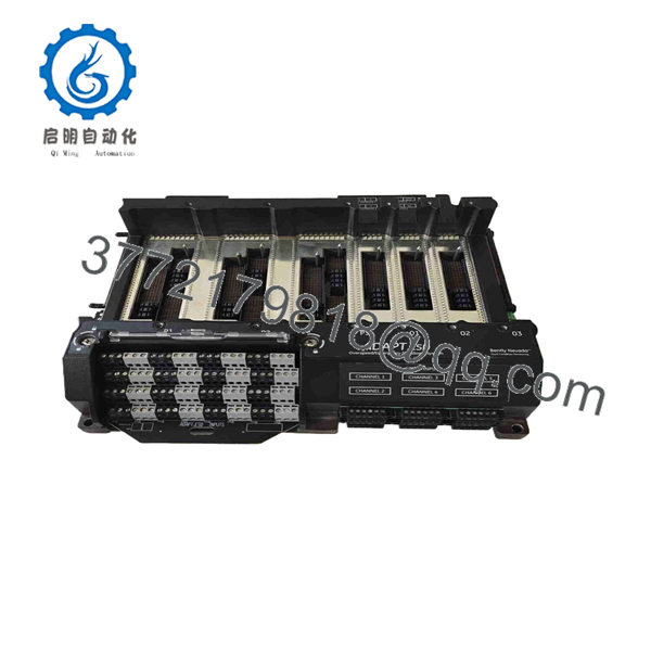
3701/55 289761-01
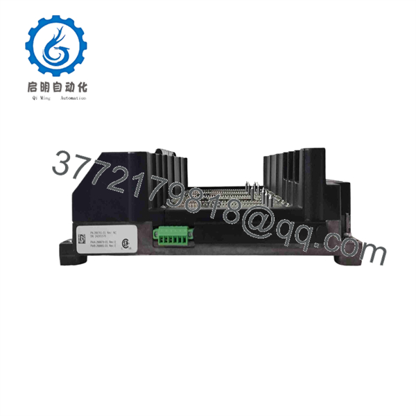
3701/55 289761-01
Frequently Asked Questions (FAQ)
Q1. What exactly is Bently Nevada 289761-01?
289761-01 is the ADAPT ESD Terminal Base Assembly for the 3701/55 system. It is a system component that provides the terminal and mechanical interface for the ADAPT ESD modules. Bently Nevada’s published documentation lists it separately from the 323174-01 CPU and 323073-series relay output modules.
Q2. Is 289761-01 the complete 3701/55 emergency shutdown controller?
No. This distinction matters when ordering. 289761-01 is the terminal base assembly, while the 3701/55 system uses additional components such as the 323174-01 ADAPT ESD CPU and relay output modules.
Q3. Can I replace 289761-01 while the ESD system is powered?
Treat this as a de-energized maintenance task unless the applicable Bently Nevada documentation and site safety procedure explicitly authorize another method. This is an emergency shutdown system, so casually removing a terminal base under power is not an acceptable substitution procedure.
Q4. What should I verify before ordering a replacement?
Check the 3701/55 system designation and 289761-01 part number against the installed hardware. Also photograph the complete assembly, terminal wiring, CPU module, relay modules, and enclosure arrangement. This prevents the common mistake of ordering a related 3701/55 component instead of the terminal base.
Q5. Does the 289761-01 require a specific mounting orientation?
Yes. The 3701/55 documentation specifies that the terminal base should be mounted vertically, with the power supply terminal exiting horizontally for heat dissipation. The installation drawing also calls for a minimum enclosure depth of 9 in.
Q6. Is 289761-01 obsolete?
The available Bently Nevada documentation continues to identify 289761-01 as an accessory for the 3701/55 ADAPT ESD system, but documentation availability does not establish current OEM production or stock status. For procurement, verify the exact condition, date code, packaging, and traceability of the physical unit being quoted.
Q7. What condition should I expect when buying a replacement?
Do not rely on a generic “new” description. Confirm whether the offered unit is Factory Sealed, New Original/New Surplus, or Refurbished (tested) and request photographs of the actual nameplate and packaging. If functional testing has been performed, request the applicable test report rather than accepting an unsupported “tested” claim.



