
 WhatsApp: +86 16626708626
 Email:
  Phone: +86 16626708626
Description
Key Technical Specifications
| Parameter | Specification |
|---|---|
| Manufacturer | Bently Nevada |
| Part Number | 84661-50 |
| Product Type | Velomitor Interconnect Cable |
| Cable Series | 84661 |
| Cable Length | 50 ft / approximately 15.2 m |
| Conductor Configuration | 2-conductor twisted pair |
| Conductor Size | 22 AWG / approximately 0.382 mm² |
| Shielding | Overall shield |
| Armor | Stainless-steel armor |
| Transducer-End Connection | Sealed female connector |
| Monitor-End Termination | Tinned/bare leads or terminal lugs |
| Voltage Rating | 300 V AC/DC reported by supplier documentation |
| Temperature Range | -29 °C to +121 °C (-20 °F to +250 °F) |
| Minimum Listed Length | 3 ft / approximately 0.91 m |
| Maximum Listed Length | 96 ft / approximately 29 m |
The 50 ft ordering option is directly associated with the “-50” suffix in multiple product records. Technical listings also consistently identify the cable as a 22 AWG shielded/armored interconnect cable for Bently Nevada vibration instrumentation.
Some reseller pages publish conflicting values for temperature, cable construction, weight, and connector terminology. For procurement, the part number and exact factory cable construction should take precedence over generic reseller specifications. In particular, claims such as M12 connectors or 100 Mbps data transmission found on some pages do not match the Velomitor cable descriptions and should not be treated as specifications for 84661-50.
Product Introduction
The Bently Nevada 84661-50 is a 50 ft Velomitor interconnect cable used to carry vibration-transducer signals between compatible Bently Nevada sensors and monitoring equipment. The cable uses a shielded two-conductor construction and is available with a sealed sensor-side connector and terminal-lug termination at the monitor side.
The armored construction is intended for industrial machinery installations where the cable route can be exposed to mechanical abrasion, vibration, electrical interference, and elevated temperatures. Exact sensor and monitor compatibility should be checked against the installed Bently Nevada system documentation before replacement.
Installation & Configuration Guide
Stage 1 — Pre-Installation
Estimated time: 15–30 minutes
- Apply the plant’s LOTO procedure before disconnecting the vibration-monitoring circuit.
- Identify the existing cable at both the transducer and monitoring-system ends.
- Photograph:
- Sensor connector orientation
- Monitor-side termination
- Cable routing
- Shield/ground connections
- Record the existing cable part number and length.
- Prepare:
- ESD wrist strap where electronic equipment will be accessed
- Multimeter
- Screwdrivers
- Cable labels
- Smartphone/camera
- Confirm that the replacement is specifically 84661-50 and not another 84661 length option.
⚠️ Do not select cable length by appearance alone. The “-50” suffix corresponds to the 50 ft configuration.
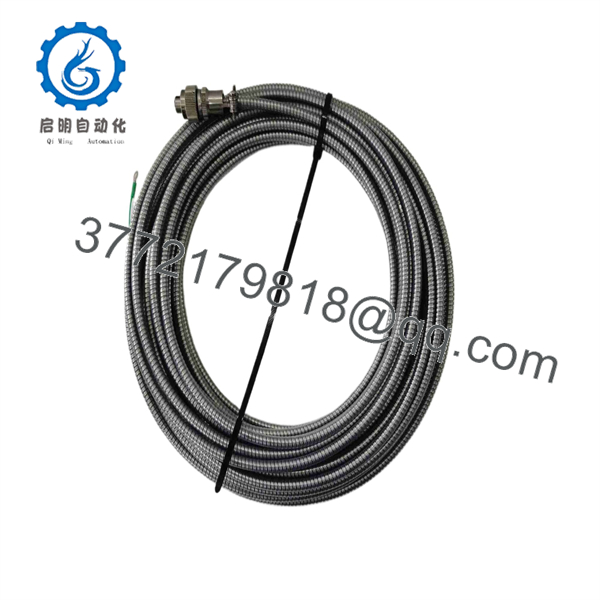
84661-50
Stage 2 — Remove the Existing Cable
Estimated time: 20–40 minutes
- Confirm that the machinery is in the appropriate maintenance state.
- Isolate the applicable monitoring circuit according to plant procedures.
- Label the sensor end and monitor end before disconnecting anything.
- Disconnect the cable from the velocity transducer.
- Remove the monitor-side terminal connections one at a time.
- Preserve the original shield/ground arrangement.
- Remove cable clamps and routing hardware.
- Pull the cable without excessive force.
- Inspect the removed cable for:
- Crushed armor
- Broken conductors
- Damaged connector boot
- Corrosion
- Moisture ingress
- Abrasion
Keep the removed cable until the replacement has passed continuity and functional checks.
Stage 3 — Install the Replacement
Estimated time: 30–45 minutes
- Compare the replacement cable against the removed cable.
- Verify the 84661-50 part number and cable length.
- Route the cable using the original path where practical.
- Avoid sharp bends and excessive mechanical tension.
- Connect the sensor-side connector completely.
- Reproduce the original monitor-side termination.
- Reconnect the shield according to the system wiring documentation.
- Secure the cable so that machinery vibration does not transfer excessive mechanical load into the sensor connector.
- Check that the cable does not contact hot surfaces, rotating equipment, or sharp edges.
Pre-Power Checklist
- Part number 84661-50 verified
- 50 ft cable length verified
- Sensor connector fully seated
- Monitor termination verified
- Shield connection verified
- Cable routing secured
- No crushed armor
- No excessive bend or tension
⚠️ Do not improvise the shield termination. Incorrect grounding can introduce electrical noise into low-level vibration measurements.
Stage 4 — Electrical and Functional Testing
Estimated time: 20–40 minutes
- Use a multimeter to check conductor continuity before returning the circuit to service.
- Check for unintended conductor-to-conductor shorts.
- Verify shield continuity where required by the system wiring.
- Confirm that the sensor connector is mechanically secure.
- Restore the monitoring system according to the plant procedure.
- Observe the associated monitor channel for fault or signal-loss indications.
- Compare the vibration reading with the pre-maintenance condition.
- Confirm that the channel returns to its expected operating state.
- Record the cable part number and installation date in the maintenance record.
⚠️ A cable replacement should not be used as an opportunity to change the monitoring-channel configuration. If the vibration level changes unexpectedly after cable replacement, investigate wiring polarity, shield termination, connector seating, sensor condition, and monitor-channel configuration before altering alarm settings.
FAQ
Q1. What is Bently Nevada 84661-50?
It is a Velomitor interconnect cable, part of the Bently Nevada 84661 cable family. The “-50” configuration is identified as a 50 ft cable.
Q2. Is 84661-50 a vibration sensor?
No. It is a cable assembly, not the velocity transducer itself. Its job is to provide the electrical connection between compatible vibration instrumentation and the monitoring equipment.
Q3. What is the cable length?
The 84661-50 ordering configuration is 50 ft, approximately 15.2 m.
Q4. What conductor size does 84661-50 use?
Available product records identify the cable as a two-conductor, twisted, shielded 22 AWG cable, approximately 0.382 mm² per conductor.
Q5. Can I replace another 84661 cable with 84661-50?
Only if the required cable length and system installation permit it. The 84661 family includes different length configurations. Before ordering, verify the existing cable’s complete part number, physical route, connector arrangement, and required length.
Q6. Can the cable be spliced if it is damaged?
For a critical machinery vibration-monitoring circuit, replacing the complete cable assembly is preferable to an improvised splice. A splice can compromise shielding, mechanical protection, moisture resistance, and signal integrity.
Q7. Is 84661-50 compatible with every Bently Nevada vibration system?
No. Compatibility should be established from the specific transducer, monitor channel, connector, and wiring documentation. Some supplier listings associate the cable with Velomitor and compatible vibration-monitoring equipment, but those listings should not replace the OEM system documentation.
Q8. What condition should I specify when purchasing?
For a legacy vibration-monitoring installation, specify the condition explicitly: New Original / Factory Sealed, New Surplus, or Tested/Refurbished. Also request photographs of the actual connector and termination if the cable will replace a critical machinery-monitoring loop.



