
 WhatsApp: +86 16626708626
 Email:
  Phone: +86 16626708626
Description
- Key Technical Specifications
| Parameter | Specification |
| Supply Voltage | 24 V DC (18 to 31.2 V DC tolerance, per EN 61131-2) |
| Current Load | 120 mA max (internal logic from 24 V DC supply) |
| Fieldbus Interface | CAN bus via CANtrol backplane / terminal connections |
| Communication Protocol | CANopen (DS301 profile) or proprietary Berghof CANtrol protocol |
| Digital Inputs | 16 channels, 24 V DC (Type 1 sink/source) |
| Input Filter Delay | 3.0 ms typical |
| Digital Outputs | 16 channels, 24 V DC transistor outputs |
| Output Current Capacity | 0.5 A continuous per channel (short-circuit protected) |
| Total Module Output Load | 8.0 A maximum continuous aggregate load across all 16 channels |
| Electrical Isolation | 500 V RMS optocoupler isolation between bus/logic and field I/O |
| Field Wiring Terminals | Pluggable screw/spring-cage terminal blocks |
| Mounting & Form Factor | Standard 35 mm DIN-rail mounting; compact IP20 enclosure |
| Operating Temperature | 0 to +55°C (32 to 131°F) |
- Product Introduction
The Berghof QDIO 1616-0,5 is a high-density, 32-point digital expansion module engineered for the Berghof CANtrol automation system architecture. Equipping your controller rack with 16 discrete 24 V DC inputs and 16 short-circuit-proof 0.5 A transistor outputs, it consolidates machine-level I/O points into a single DIN-rail footprint, eliminating extra fieldbus couplers and panel wiring complexity.
Communicating across the high-speed CANtrol internal bus or CANopen network, the module transfers deterministic cyclic I/O data directly to Berghof EC2000/DC2000 series PLCs. Plant maintenance teams and system integrators specify the QDIO 1616-0,5 when maintaining or retrofitting legacy Berghof control cabinets in plastics machinery, packaging lines, and customized industrial processing systems.
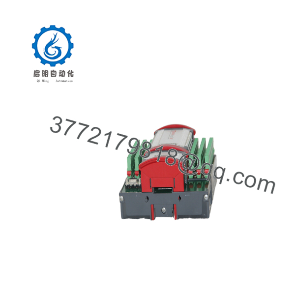
QDIO 1616-0,5
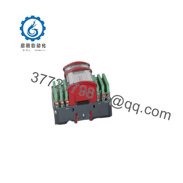
QDIO 1616-0,5
- Troubleshooting Quick Reference
| Symptom | Possible Cause | Relevance to this Part | Quick Check Method | Recommendation |
| Power LED OFF / Module dead | 24 V DC auxiliary supply missing or inverted polarity | ✅ High | Measure voltage across 24V and 0V power terminals on the module header | Check external 24 V DC power supply and wiring polarity. If power is verified >21 V DC, internal fuse/DC-DC converter is damaged. Replace module. |
| CAN bus fault LED active / No comms | Node address mismatch, wrong baud rate, or missing 120 Ω bus terminator | ✅ High | Verify DIP switch node ID setting; measure CAN_H to CAN_L resistance with power OFF | Ensure CANopen node address matches PLC project. Verify line termination resistance measures ~60 Ω (two 120 Ω resistors in parallel at network ends). |
| Output LED ON but load doesn’t actuate | External output supply voltage missing or blown channel protection | ✅ High | Measure voltage between the specific output pin and 0 V DC while output is forced high | Check the dedicated 24 V DC field supply bank powering the output drivers. If voltage is present on power terminal but 0 V at pin, output driver transistor is blown. |
| Input LED fails to illuminate when sensor trips | Sensor signal voltage < 15 V DC or incorrect PNP/NPN wiring logic | ❌ Low | Measure voltage at the input terminal relative to 0 V DC when sensor triggers | Confirm sensor output supplies at least 15 V DC for a logic high state. Verify field wiring matches module input common terminal configuration. |
- Frequently Asked Questions (FAQ)
Q: Does the QDIO 1616-0,5 require software configuration before it will communicate on a CANopen network?
A: Yes. The module requires a valid CANopen node ID (set via onboard DIP switches or software parameters) and bit rate selection matching your master controller configuration. You must import the official Berghof EDS file into your CoDeSys or CANtrol configuration tool to map the 16 inputs and 16 outputs into the system process image.
Q: Can I drive inductive loads like solenoid valves directly from the 0.5 A outputs?
A: Yes, but with caution. While the output drivers feature built-in electronic short-circuit and thermal protection, switching unsuppressed inductive loads (solenoids, contactor coils) causes inductive voltage spikes. Always install external flyback diodes or RC suppressors directly across inductive loads to prevent premature output driver degradation.
Q: What is the difference between the QDIO 1616-0,5 and standard QIO modules?
A: The QDIO designation specifies a dual-function, high-density digital module containing both inputs and outputs (16 In / 16 Out) on a single card. The “0,5” suffix explicitly designates the 0.5 Ampere maximum continuous switching limit per output transistor.
Q: Are the green terminal strips removable for fast field servicing?
A: Yes. The module utilizes two-piece pluggable terminal headers. You can unplug the wired terminal blocks directly from the board when replacing a faulted unit, eliminating the need to label and disconnect individual wires during emergency field maintenance.
Q: How do you verify performance on surplus Berghof QDIO 1616-0,5 units before dispatch?
A: Every unit passes a rigorous 5-step SOP quality inspection. We mount the card into a live Berghof CANtrol test rack, run continuous CANopen data cyclic exchanges, cycle all 16 input optocouplers, perform a 24-hour continuous 0.5 A resistive load test across all 16 transistor outputs, and execute a 500 V Megger insulation check prior to ESD sealing.



