
 WhatsApp: +86 16626708626
 Email:
 Phone: +86 16626708626
Description
3. Key Technical Specifications
- Rated load (RL): 20 kN (approx. 4,500 lb)
- Combined error (terminal): ±0.05% RO
- Repeatability: 0.01% RO
- Rated output (RO): 2.040 mV/V (±0.25% tolerance)
- Input resistance: 350 Ω ±3 Ω
- Output resistance: 350 Ω ±3 Ω
- Recommended excitation: 10 V DC or AC (maximum 18 V)
- Safe overload: 200% RL
- Ultimate overload: 300% RL
- Safe side load: 100% RL
- Safe uplift: 100% RL
- Creep (30 min at RL): ±0.03% RL
- Temperature range: –40 to +105 °C
- Protection class: IP67
- Material: Stainless steel
- Cable: Typically 5 m or 10 m 4-wire shielded
- Certifications: ATEX, IECEx, FM, CSA (hazardous locations available)
4. Product Introduction
The BLH Nobel KIS-2-20KN is a stainless-steel load cell from the KIS-2 series designed for accurate force measurement and process weighing up to 20 kN. Its double-cantilever construction provides a movable load point that tolerates high side loads and thermal expansion without significant measurement error.
Engineers use the KIS-2-20KN in batching systems, reactor vessels, conveyor weighing, web-tension control, and quality-critical force applications. The combination of ±0.05% combined error, IP67 sealing, and optional hazardous-area certifications makes it a direct replacement choice when a rugged, side-load-tolerant sensor is required.
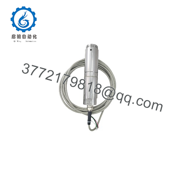
KIS-2-20KN
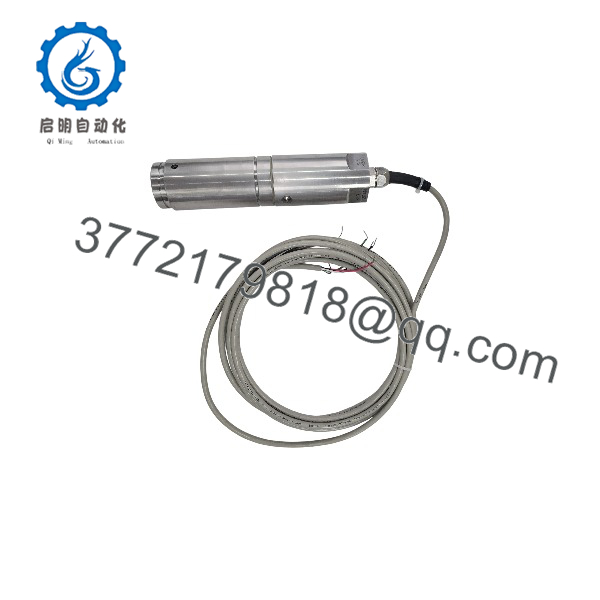
KIS-2-20KN
5. Troubleshooting Quick Reference
| Symptom | Possible Cause | Relevance to this Part | Quick Check Method | Recommendation |
|---|---|---|---|---|
| Zero output or open circuit | Cable damage or broken strain gauge | ✅ High | Measure input and output resistance (should be ~350 Ω); check continuity of all four wires | Replace cable or unit if resistance is out of tolerance |
| Unstable or drifting reading | Moisture ingress or loose connectors | ✅ High | Inspect cable entry and connectors; verify insulation resistance >4 GΩ | Dry and reseal; replace if IP67 seal is compromised |
| Reading offset under no load | Mechanical binding or residual side load | ✅ Medium | Ensure load point is free to move; check for thermal expansion constraints | Re-align mounting so the load point can float |
| Output does not reach expected mV/V | Excitation voltage incorrect or partial overload damage | ✅ High | Confirm 10 V excitation at the cell; apply known calibration weight | Recalibrate or replace if rated output cannot be achieved |
| Intermittent signal under vibration | Loose terminal or fatigued cable | ✅ Medium | Wiggle cable while monitoring output; inspect strain-relief | Secure cable and add proper strain relief |
| Excessive error under side load | Exceeded safe side-load rating | ✅ High | Verify side force remains within 100% RL | Redesign mounting or select higher-capacity unit if side loads are higher |
If the above checks do not resolve the issue, provide photos of the installation, measured resistance values, and excitation voltage to technical support.
6. Frequently Asked Questions (FAQ)
Q: What is the difference between the KIS-2-20KN and other KIS-2 capacities?
A: The electrical specifications (mV/V, resistance, accuracy) are the same across the series. Only the rated load changes. The 20 kN version is sized for applications that need that specific force range while retaining the full side-load capability of the design.
Q: Can the KIS-2-20KN handle continuous side loading?
A: Yes. The double-cantilever design tolerates safe side loads up to 100% of rated load without damage or significant error. This is one of the main reasons the cell is chosen for applications with thermal expansion or misalignment.
Q: Is the unit suitable for hazardous areas?
A: Standard units can be ordered with ATEX, IECEx, FM, or CSA certification for explosive atmospheres. Confirm the exact certification marking on the nameplate of the unit you receive.
Q: What cable length is supplied?
A: Most units ship with a 5 m or 10 m 4-wire shielded cable. Longer custom lengths are available from the factory but are not always stocked in surplus inventory.
Q: Does the -20KN require a special mounting kit?
A: The load cell itself can be installed directly, but an optional weigh-module mounting assembly is often used for process vessels to provide proper load introduction and overload protection. Verify your mechanical design before ordering.
Q: Why is the aftermarket price lower than a new factory quote?
A: These units are new surplus or carefully tested stock. They meet original electrical and mechanical specifications and carry a standard warranty, but they are not always in current factory packaging.
Q: How do I verify the cell before installation?
A: Measure input and output resistance (both ~350 Ω), apply the recommended 10 V excitation, and confirm zero balance is within ±5% RO. A known calibration weight or shunt calibration can then be used to check span.



