
 WhatsApp: +86 16626708626
 Email:
  Phone: +86 16626708626
Description
Key Technical Specifications
| Parameter | Value |
|---|---|
| Manufacturer | Bombardier Transportation |
| Model | DCC2223A |
| Part Number | 3EST125-977 |
| Product Type | Drive Control Unit |
| Application | Railway vehicle control / traction systems |
| System Family | DCC / MITRAC |
| Communication | MVB reported by secondary sources |
| Service Interface | RS-485 reported by secondary sources |
| Power Supply | Variant-dependent; verify against equipment documentation |
| Operating Temperature | Variant-dependent; verify exact hardware revision |
| Mounting | Vehicle control cabinet / equipment rack, application-dependent |
| Condition | New Original, New Surplus, Used, or Refurbished depending on inventory |
Important verification note: Publicly available sources disagree substantially on the electrical and environmental specifications for DCC2223A 3EST125-977. One source identifies it as a Bombardier railway drive-control unit and gives application information, while another lists 24 VDC, MVB, RS-485, and specific processor/environmental data. Other commercial listings incorrectly describe the same part as an industrial VFD/control panel.
For procurement or replacement, do not use an unverified 24 VDC, 72–110 VDC, 750/1,500 VDC, IP65/IP67, or temperature specification as a design basis. Verify the nameplate, hardware revision, vehicle platform, and OEM documentation first.
Product Introduction
The Bombardier DCC2223A 3EST125-977 is identified in available industry records as a railway drive/control module associated with Bombardier transportation equipment. Sources associate the part with traction, braking, vehicle-control functions, and communication with other onboard control systems.
This is a legacy railway component, so exact system compatibility matters more than a nominal model-number match. Before replacing one in service, compare the complete part number, hardware revision, vehicle application, connector configuration, and software/configuration requirements against the installed unit.
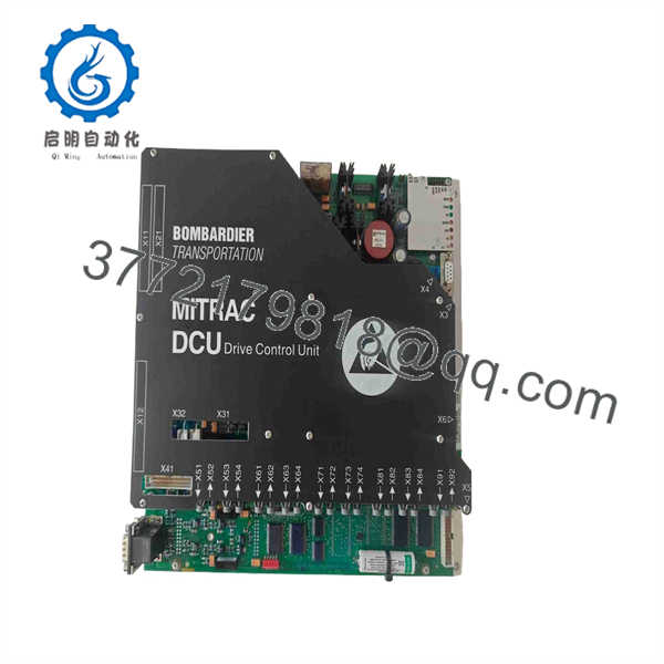
DCC2223A 3EST125-977
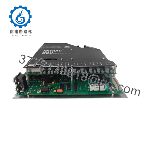
DCC2223A 3EST125-977
Installation & Configuration Guide
Stage 1: Pre-Installation Preparation — 10–15 minutes
⚠️ Safety First: This component belongs to railway equipment. Follow the vehicle manufacturer’s maintenance procedure rather than applying a generic PLC replacement procedure.
- Place the vehicle or test system into the approved maintenance state.
- Isolate the applicable auxiliary and traction power sources.
- Apply the required lockout/tagout or railway electrical isolation procedure.
- Verify absence of hazardous voltage with an appropriately rated meter.
- Wear an ESD wrist strap before handling the electronic module.
- Photograph the installed DCC2223A from several angles.
- Record:
- DCC2223A
- 3EST125-977
- Hardware/revision markings
- Serial number
- Connector labels
- Existing diagnostic indications
- Back up the applicable vehicle-control configuration before removing the module, where the platform permits it.
⚠️ Do not assume the module is a conventional 24 VDC PLC card. Public documentation for this exact part is inconsistent, so the installed vehicle documentation must control the electrical procedure.
Stage 2: Removing the Old Module — 10 minutes
- Confirm electrical isolation before disconnecting the module.
- Photograph every connector and cable position.
- Label connectors that do not already have permanent identification.
- Release the mechanical retaining hardware.
- Disconnect connectors using their locking mechanisms rather than pulling the cable.
- Remove the module straight from its mounting arrangement.
- Inspect the connector pins and mating surfaces.
- Check for:
- Bent contacts
- Corrosion
- Contamination
- Heat discoloration
- Damaged locking mechanisms
- Evidence of water or condensation
❗ Keep the removed module until commissioning is complete. Its hardware label and connector arrangement may be needed to resolve a revision mismatch.
Stage 3: Installing the New Module — 10 minutes
- Verify the complete identification: DCC2223A / 3EST125-977.
- Compare hardware and revision markings against the original.
- Confirm that the replacement’s connector arrangement matches the vehicle installation.
- Inspect connector pins before insertion.
- Install the module in the original orientation.
- Secure the mechanical retaining hardware.
- Reconnect every connector according to the photographs and wiring documentation.
- Confirm that each connector locking mechanism is fully engaged.
- Restore cable retention and strain relief.
Self-Checklist:
- confirmed
- 3EST125-977 confirmed
- Hardware revision checked
- Connector positions verified
- Connector locks engaged
- Mounting hardware secured
- Configuration backup available
Stage 4: Power-On & Testing — 10–20 minutes
- Perform a complete visual inspection before energizing.
- Verify that no tools or loose hardware remain inside the cabinet.
- Restore power according to the approved vehicle procedure.
- Observe module status LEDs or diagnostic indicators.
- Check the vehicle control system for module recognition.
- Check the applicable communication network.
- Review active and historical diagnostic codes.
- Confirm communication with the associated traction, brake, or vehicle-control equipment.
- Perform the manufacturer’s prescribed static test.
- Complete a controlled functional test before returning the vehicle to service.
⚠️ Do not substitute a generic Ethernet/PROFIBUS/Modbus commissioning procedure for the vehicle OEM’s test procedure. Available commercial descriptions of this part conflict on its communication interfaces. Some sources specifically identify MVB and RS-485, while others incorrectly list industrial Ethernet protocols.
Technical Pitfalls — What Usually Causes Rework
1. ❗ Part-Number Similarity
A matching designation is not sufficient by itself. The full 3EST125-977 number and hardware revision need to match the application.
2. ❗ Wrong Electrical Specification
This is the biggest procurement trap. Online listings provide incompatible voltage figures for the same part. Treat those values as unverified until confirmed against the actual equipment documentation.
3. Connector Configuration
Railway control equipment can use application-specific harnesses. Photograph the original installation before removal and compare connector keys, labels, and pin assignments.
4. Software / Configuration Compatibility
A physically compatible replacement may still require the correct application configuration or software revision. Record the old unit’s configuration and diagnostic data before removal whenever the platform permits.
5. Environmental Qualification
Do not assume that a generic IP rating or temperature specification applies to every installation. Railway equipment qualification depends on the vehicle application and exact hardware variant.
Frequently Asked Questions (FAQ)
Can I hot-swap the ?
Do not assume that it is hot-swappable. Remove and install the module only under the vehicle manufacturer’s approved isolation procedure. The correct procedure depends on the Bombardier vehicle platform and electrical architecture.
Is 3EST125-977 obsolete?
It should be treated as a legacy/older railway component for sourcing purposes. Current availability appears to depend on remaining industrial inventory and specialist spare-parts channels. Public listings do not establish a current Bombardier replacement number.
Is 3EST125-977 the same product as ?
Available listings consistently associate with 3EST125-977, but the safest purchasing practice is to specify both identifiers.
Will replacing the module erase the vehicle configuration?
The answer depends on how the particular vehicle platform stores its application configuration. Do not assume configuration retention. Record or back up the relevant configuration before removal and follow the Bombardier maintenance procedure.
What should I send a supplier before ordering?
Send a clear photograph of the complete nameplate showing , 3EST125-977, revision, and serial information, plus photographs of the connectors. Also provide the vehicle/platform designation if available.
Why do online specifications for this part conflict?
Because several third-party sellers appear to have classified the same reference differently. Search results describe it variously as a railway drive-control unit, safety computer, control panel, and industrial drive module.
For that reason, I would not publish the conflicting voltage, processor, memory, IP rating, or temperature figures as confirmed specifications without the OEM documentation or a clear photograph of the actual unit.
What condition should I request?
For a critical railway spare, specify the required condition explicitly: New Original / New Surplus, Used Tested, or Refurbished Tested. Ask for photographs of the actual unit, nameplate, serial number, test evidence, and warranty terms before purchasing.



