
 WhatsApp: +86 16626708626
 Email:
  Phone: +86 16626708626
Description
Key Technical Specifications
- Manufacturer: Bosch Rexroth
- Legacy Brand Reference: Indramat
- Part Number: 0608750112
- Formatted Order Number: 0 608 750 112
- Module Identification: LT353
- Product Type: Power module, servo amplifier module, or drive controller module
- System Family: Bosch Rexroth 350 electric tightening system
- Primary Application: Electric tightening spindle drive and automated fastening line control
- Listed DC Bus Rating: 330 V DC
- Listed Current Rating: 3.5 A
- Motor Application: Tightening-spindle motor control
- Control Purpose: Controlled torque and angle fastening through the associated Rexroth tightening architecture
- Mounting Requirement: Verify original chassis, card guides, cooling path, connectors, and mechanical retention
- Configuration Requirement: Confirm spindle model, controller configuration, motor cable, feedback cable, and parameter set before replacement
- Replacement Rule: Match 0608750112, 0 608 750 112, and LT353; do not substitute a generic analog I/O module or unrelated Rexroth drive
Supplier records consistently identify 0608750112 / 0 608 750 112 as a Bosch Rexroth LT353 power or servo-amplifier module for tightening systems, with a 330 V DC and 3.5 A rating. A generic listing that calls it an analog I/O module conflicts with the LT353 drive and power-module records and should not be used for procurement or installation.
Product Introduction
The Bosch Rexroth 0608750112, also marked 0 608 750 112 and LT353, is a power and servo-amplifier module for Rexroth electric tightening systems. It drives the tightening-spindle motor within automated fastening equipment, where the control system manages the programmed tightening sequence and monitors fastening results.
This part is normally purchased as an exact replacement for an installed LT353 drive module. Correct replacement requires more than matching the base number: confirm the drive label, 330 V DC bus arrangement, spindle motor, feedback interface, controller generation, firmware or parameter set, cooling condition, and cabinet wiring before energizing the replacement.
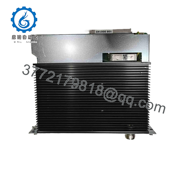
0608750112
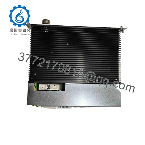
0608750112
Troubleshooting Quick Reference
| Symptom | Possible Cause | Relevance to This Part | Quick Check Method | Recommendation |
|---|---|---|---|---|
| Tightening spindle does not enable | Safety circuit open, controller inhibit active, missing DC bus, failed drive, motor cable fault | ⚠️ Medium | Check safety relay status, controller enable command, emergency-stop circuit, DC bus presence, and drive diagnostic indication | Clear safety and controller inhibits before replacing the module |
| No drive power or no spindle movement | Blown upstream fuse, missing DC bus, failed power supply, poor module seating, failed drive | ✅ High | Under approved lockout/tagout, measure the specified DC bus at the drive input and inspect fuses, contactors, connectors, and board seating | Verify the supply and bus circuit before replacing the module |
| Spindle moves but cannot reach torque | Mechanical spindle issue, incorrect tightening program, motor feedback fault, drive current limit, worn gearbox | ⚠️ Medium | Compare commanded versus actual torque and angle; inspect spindle mechanics, motor connector, and feedback cable | Check the spindle and programmed job first; replace the drive only after confirming electrical faults |
| Repeated overcurrent or drive fault | Shorted motor winding, damaged motor cable, seized spindle, failed output stage | ✅ High | Isolate power, measure motor phase resistance and insulation according to OEM procedure, then inspect cable for abrasion or pin damage | Correct motor, cable, or mechanical-load fault before installing a replacement |
| Drive overheats or trips after running | Failed cooling fan, blocked airflow, contaminated heat sink, high duty cycle, deteriorated output stage | ✅ High | Inspect cabinet filters, fan operation, cooling path, heat-sink cleanliness, and ambient temperature | Restore cooling and investigate load before replacing the drive |
| Torque results vary between cycles | Loose motor feedback connector, worn spindle, parameter mismatch, unstable DC bus, grounding issue | ⚠️ Medium | Review controller tightening curves and fault history; inspect motor/feedback cable shielding and connector retention | Verify mechanical and parameter causes before condemning the |
| Fault begins immediately after replacement | Wrong drive variant, parameter mismatch, incorrect connector, damaged feedback cable, incompatible controller revision | ✅ High | Compare old and replacement labels, connectors, jumpers, firmware labels, and parameter backup; restore approved configuration | Stop commissioning until model, parameters, and wiring are confirmed |
| Drive status is normal but station remains faulted | PLC sequence issue, safety interlock, tooling clamp fault, part-present sensor, controller network fault | ❌ Usually Low | Check station sequence diagnostics, safety status, sensor inputs, and controller fault log | Do not replace the drive until the station permissives are confirmed |
| Visible burn marks or damaged terminals | DC bus surge, shorted output, loose high-current connection, failed contactor, contamination | ✅ High | Inspect under good lighting for discolored components, damaged connectors, overheated terminals, and carbon tracking | Remove from service and correct the root cause before fitting another module |
Field warning: A failed tightening drive is often the result, not the cause. A seized spindle, damaged motor cable, shorted winding, weak cooling fan, or loose high-current terminal can take out a replacement module just as quickly as the original. Check the motor and mechanical load before energizing a replacement .
❗ 330 V DC is hazardous: This is not a 24 V DC I/O module. The is listed as a 330 V DC, 3.5 A drive controller or power module. Follow the equipment lockout/tagout procedure, verify the DC bus has discharged using a properly rated meter, and observe the manufacturer’s discharge time before handling the module.
❗ Do not confuse it with analog I/O: One generic web listing calls 0608750112 an analog input/output module, but the specific records identify it as a tightening-system servo amplifier or power module. Do not apply field analog signals or rack I/O wiring to this drive.
❗ Parameter backup comes before removal: Before replacing the unit, save or record the tightening controller’s spindle assignment, job programs, torque limits, angle limits, speed profiles, error masks, and calibration data. A drive that powers up with incorrect parameters can create rejected joints, tool faults, or unsafe motion.
❗ Motor-feedback cable errors are common: Photograph and label every motor and feedback connector before disconnecting them. Check shielding, connector locks, pin condition, cable strain relief, and routing away from high-current conductors. A feedback fault can look exactly like a failed servo amplifier.
❗ Cooling cannot be ignored: Check cabinet filters, fans, heat-sink surfaces, exhaust clearance, and ambient temperature. I have seen a drive replaced twice in one week because the failed cabinet fan was never repaired. The new module ran hot, tripped, and became the next “bad drive.”
❗ ESD and connector handling: Use a grounded wrist strap and keep the module in antistatic packaging until installation. Never force a connector. If it does not align and seat with normal pressure, stop and verify the module, cable, and connector keying.
Keep these checks in mind and you will save yourself 90% of typical rework time. If the problem remains unresolved, send technical support photographs of the drive label, fault code, controller screen, spindle model, motor and feedback connectors, measured DC bus voltage, and recorded tightening trace.
Frequently Asked Questions
What is Bosch Rexroth 0608750112?
Bosch Rexroth 0608750112, also identified as 0 608 750 112 and , is a power or servo-amplifier module used in Rexroth electric tightening systems. It controls the tightening-spindle motor in automated fastening equipment.
Is 0608750112 an analog I/O module?
No. Do not rely on generic online listings that call it analog I/O hardware. The specific references describe 0608750112 as a power module, servo amplifier, or drive controller with a listed 330 V DC, 3.5 A rating for tightening applications.
What voltage and current rating does the module use?
Available and distributor records list 330 V DC and 3.5 A for the 0608750112 module. Confirm the exact cabinet DC bus, fuse rating, supply architecture, discharge procedure, and drive revision from the installed Rexroth documentation before testing or replacement.
Can I replace 0608750112 with another Rexroth drive that looks similar?
No. Tightening-system drives are matched to the controller, spindle motor, feedback system, power bus, connectors, and configured fastening program. A similar-looking Rexroth card may fit mechanically while using different motor control, current rating, software parameters, or connector assignments. Match the complete identification and verify OEM-approved interchangeability.
Can I hot-swap the servo amplifier?
No. Do not hot-swap it. The module is part of a high-energy DC drive system. Remove power using the approved lockout/tagout procedure, wait for the DC bus to discharge, verify the absence of hazardous voltage with a properly rated meter, and follow the Rexroth service procedure before removing or installing the module.
Will I lose tightening programs when I replace the drive?
The tightening programs often reside in the controller, but drive-related parameters, calibration values, spindle assignments, firmware dependencies, or fault history may be associated with the drive system. Back up the controller project and record the complete installed configuration before removal. After replacement, perform the required commissioning, test-fastening, torque verification, and quality validation before releasing the station to production.
Why does the replacement drive fault immediately after installation?
The usual causes are a wrong drive variant, incorrect or missing parameters, damaged motor cable, damaged feedback cable, a shorted motor winding, a seized spindle, poor cooling, or a DC bus issue. Do not install a second replacement until the motor, cable insulation, connector pins, mechanical load, supply bus, and controller configuration have been checked.
Is Bosch Rexroth 0608750112 obsolete?
Treat it as a legacy tightening-system spare. Public availability is mainly through independent automation suppliers and surplus sellers, including listings for used, refurbished, and new stock. Confirm actual inventory, module condition, revision, testing method, warranty, and return terms before issuing a purchase order.
Why is a New Surplus module cheaper than a factory replacement?
New Surplus stock can come from unused service inventory, production-line upgrades, cancelled projects, or warehouse liquidation. It may be unused but lack original factory packaging. With a power-drive module, storage history matters: ask about moisture exposure, connector corrosion, capacitor condition, cooling hardware, label verification, test method, and warranty.
What testing should a supplier perform before shipment?
A valid inspection and test process for a Bosch Rexroth 0608750112 should include:
- Verify the full 0608750112, 0 608 750 112, and labels, plus any revision or serial identifiers
- Photograph the front, rear, connectors, heat sink, cooling surfaces, mounting hardware, and all labels
- Inspect for corrosion, overheated components, damaged board edge contacts, bent pins, cracked housings, rework marks, and contamination
- Perform insulation-resistance and ground-continuity checks only according to the applicable drive-service procedure
- Test in a compatible Rexroth 350 tightening-system fixture with the correct spindle motor, controller, feedback cable, and DC bus
- Verify power-up, enable logic, fault-free operation, motor direction, stable speed response, and feedback recognition
- Run the drive under a controlled load while monitoring current draw, temperature, and fault status
- Confirm cooling-fan operation and cabinet airflow requirements where applicable
- Record the test fixture, DC bus voltage, motor type, test duration, load condition, observed diagnostics, and result
- Package in ESD-safe material with connector protection, foam support, heavy-duty boxing, QC sign-off, and written warranty terms
Test videos and photographs should be available upon request. “Powers on” does not prove a tightening drive is fit for service; the supplier should verify controlled motor operation and stable behavior under load.



