
 WhatsApp: +86 16626708626
 Email:
  Phone: +86 16626708626
Description
Key Technical Specifications
| Parameter | Value |
|---|---|
| Manufacturer | Bosch Rexroth / Indramat |
| Exact Type Code | DKC01.3-040-7-FW |
| Product Family | ECODRIVE03 / DKC |
| Product Type | AC servo drive controller |
| Design Version | 3 |
| Type Current | 40 A |
| Voltage Category | 7 |
| DC-Bus Nominal Voltage | 700 V |
| Main Input Voltage | 380–480 V AC class; verify exact nameplate limits |
| Input Frequency | 50–60 Hz |
| Control Voltage | 24 V DC |
| Control Power | Approximately 21 W |
| Maximum Input Current | 16 A |
| Maximum Output Voltage | 800 V |
| Maximum Output Frequency | 1,000 Hz |
| Continuous Power Dissipation | 180 W |
| Protection Rating | IP20 |
| Approx. Dimensions | 410 × 80 × 250 mm |
| Approx. Weight | 5.1 kg |
| Firmware | Separate/application-dependent |
| Typical Motor Family | Rexroth Indramat servo motors; exact motor compatibility must be verified |
The published specifications above are consistent across available DKC01.3-040-7-FW references for the 40 A unit, including 380–480 V input, 700 V DC bus, IP20 enclosure, and approximately 410 × 80 × 250 mm dimensions.
Important compatibility point: the FW suffix is not a generic firmware version. The ECODRIVE03 documentation states that firmware specifying the drive’s functions must be ordered separately. Therefore, the complete firmware/module identification matters when replacing an installed unit.
Product Introduction
The Bosch Rexroth / Indramat DKC01.3-040-7-FW is an ECODRIVE03 servo drive controller with a 40 A type-current rating and 700 V DC-bus class. It controls matched Indramat servo motors in machine-tool, packaging, handling, assembly, and other legacy motion-control equipment.
This is a legacy drive, so the complete type code and firmware configuration matter more than the front-panel designation alone. Bosch Rexroth reference records identify R911279426 and R911276813 as material/reference numbers associated with this type code, illustrating why the nameplate should be checked before ordering.
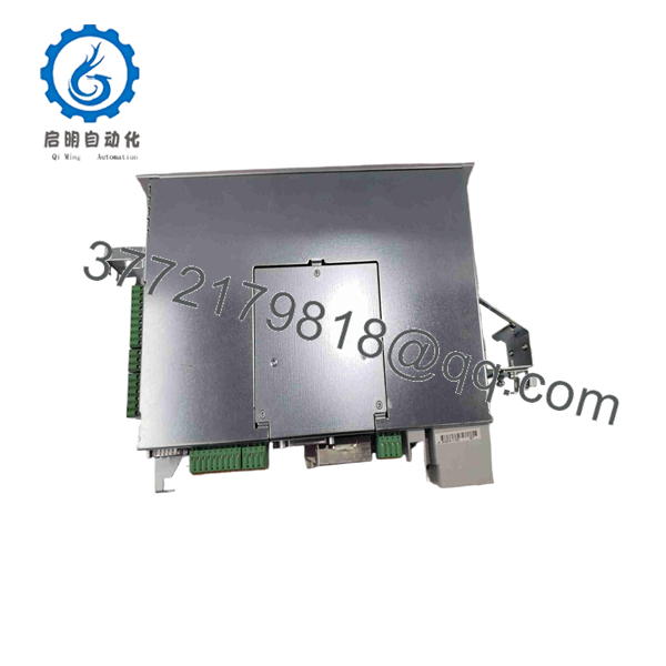
DKC01.3-040-7-FW
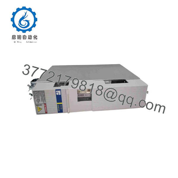
DKC01.3-040-7-FW
Installation & Configuration Guide
Stage 1: Pre-Installation Preparation — 10–20 Minutes
⚠️ Safety First: This drive operates with a high-voltage DC bus. Place the machine in its approved safe state, isolate the incoming supply, apply LOTO, and follow the Rexroth discharge procedure. Do not assume the DC bus is safe immediately after power removal.
Tools Required
- ESD wrist strap
- Insulated multimeter rated for the applicable voltage
- Appropriate screwdrivers
- Wire labels
- Smartphone/camera
- Torque-controlled screwdriver where specified
- Current ECODRIVE03 documentation
Data Backup
- Record the complete DKC01.3-040-7-FW type code.
- Photograph the complete nameplate.
- Record the Rexroth material number.
- Photograph all connectors and wiring.
- Record the firmware/programming module identification.
- Back up the existing drive parameters.
- Record the connected motor type and feedback configuration.
- Document controller interface wiring before disconnecting anything.
⚠️ Do not order or install a replacement based only on “DKC01.3.” The current class, voltage category, interface configuration, firmware, motor and feedback system all matter.
Stage 2: Removing the Old Drive — 10–15 Minutes
- Place the machine in its approved maintenance state.
- Disconnect and lock out the incoming AC supply.
- Wait the period specified by the ECODRIVE03 documentation.
- Measure the DC bus with an appropriately rated meter.
- Proceed only after the measured DC bus has fallen to the permitted safe level.
- Label incoming power, motor, control, feedback, and communication connections.
- Photograph every connector before removal.
- Disconnect the wiring without pulling on cables.
- Release the mounting hardware.
- Remove the drive while supporting its weight.
⚠️ Keep the original drive and its firmware/configuration modules until the replacement has been commissioned successfully.
Stage 3: Installing the New Drive — 10–15 Minutes
- Verify DKC01.3-040-7-FW against the original nameplate.
- Verify the material number and hardware revision.
- Confirm the required firmware module/version.
- Check the incoming supply configuration.
- Mount the drive securely in the control cabinet.
- Maintain the manufacturer’s required ventilation clearance.
- Connect protective earth first.
- Connect incoming power.
- Connect the motor power cable.
- Connect feedback and control interfaces.
- Verify shielding and grounding according to the ECODRIVE03 installation documentation.
Self-Checklist
- Exact type code matches
- Material number verified
- 40 A class verified
- Voltage category verified
- Firmware module verified
- Motor type verified
- Feedback connection verified
- PE connection secure
- Power wiring secure
- Control wiring secure
- Cabinet ventilation adequate
Stage 4: Power-On & Testing — 15–30 Minutes
- Perform a final wiring inspection before applying power.
- Energize the control supply according to the approved startup procedure.
- Check the drive display and diagnostic status.
- Verify the firmware/configuration identification.
- Confirm the motor parameters against the actual motor nameplate.
- Verify feedback recognition.
- Check command-interface status.
- Clear only documented startup faults; do not repeatedly reset an unexplained fault.
- Enable the axis at low speed.
- Verify rotation direction.
- Check actual-versus-commanded position and velocity.
- Perform a controlled machine-cycle test.
⚠️ If the drive faults immediately on enable, stop. Check motor wiring, feedback wiring, motor parameters, firmware, DC-bus conditions, and the machine controller command before continuing.
A DKC replacement is not complete simply because the display powers up. The drive, firmware, motor, feedback device, controller interface, and parameter set form one motion-control system.
Frequently Asked Questions (FAQ)
Is .3-040-7-FW still manufactured?
It is a , and current sourcing is generally through installed-base inventory, repair, remanufacturing, exchange, or surplus channels rather than normal new production. Current industrial suppliers list new, renewed, exchange, and repair options for this exact type code.
What does “040” mean in .3-040-7-FW?
According to the type-code documentation, 040 identifies the 40 A type-current class. It is not a statement that every operating condition should be run continuously at 40 A. Motor selection, switching frequency, thermal conditions, and application limits still have to be checked.
What does “FW” mean?
FW identifies a firmware-based configuration. The documentation specifically states that firmware defining the drive’s functions must be ordered separately. Do not assume any generic firmware module is acceptable. Match the installed firmware identification when sourcing a replacement.
Can I replace .3-040-7-FW with another 40 A DKC?
Not automatically. Two drives can share the 40 A designation while differing in series, interface, firmware, voltage category, motor compatibility, feedback arrangement, and parameter structure. The replacement should match the complete type code and application configuration, not just the current rating.
Does the replacement drive retain my machine parameters?
Do not assume so. Parameters can reside in the drive’s configuration/firmware environment or associated memory depending on the installation. Back up the existing parameters before removal, and record the firmware/module identification. After replacement, verify the complete parameter set before enabling motion.
What motor should be paired with this drive?
The exact motor must be selected from the Rexroth/Indramat motor-drive combination and project data. Check motor type, rated current, feedback system, brake, temperature sensor, encoder/resolver wiring, and mechanical load. A motor that physically mounts to the machine is not necessarily electrically compatible.
What should I send a supplier when requesting .3-040-7-FW?
Send clear photographs of the complete type plate, material number, firmware/programming module, connectors, and front display. Include the motor model, feedback type, machine application, input supply, fault code, required condition, quantity, and delivery requirement. This prevents a supplier from quoting a superficially similar DKC unit that cannot be commissioned in your machine.



