
 WhatsApp: +86 16626708626
 Email:
  Phone: +86 16626708626
Description
Key Technical Specifications
| Parameter | Specification |
| Main Input Voltage | 3 x AC 200 V to 480 V (±10%), 50/60 Hz |
| DC Bus Nominal Voltage | 700 V DC |
| Control Voltage Input | +24 V DC (±20%) |
| Peak Current Output | 16 A, 40 A, 100 A, or 200 A (model specific) |
| Communication Interface | SERCOS II Fiber Optic Interface (Ports X20 / X21) |
| Supported Feedback Systems | Encoder, Resolver, and MKD/MHD Motor Feedback |
| PWM Switching Frequency | 4 kHz / 8 kHz (selectable) |
| Maximum Output Frequency | Up to 800 Hz (at 8 kHz switching frequency) |
| Internal DC Bus Capacitance | 0.27 mF |
| Internal Soft-Start Resistor | 60 Ω |
| Peak Bleeder Power | 10 kW (at U_{zw} = 850 V) |
| Operating Temperature | 0°C to +45°C |
| Enclosure Protection | IP20 (Cabinet Mounting) |
Product Introduction
The Bosch Rexroth Indramat DKC02 drive controller is a high-precision digital AC servo drive designed for closed-loop motion control in the EcoDrive 03 platform. Engineeres deploy the DKC02 extensively with Indramat MKD and MHD servo motors in automated packaging lines, high-speed material handling, and CNC multi-axis automation cells. Equipped with fiber-optic SERCOS communication interfaces (ports X20 and X21), the DKC02 processes high-speed motion commands directly from a central motion controller with sub-millisecond deterministic response times.
Engineers favor the DKC02 platform for its thermal efficiency, rigid internal energy dissipation circuitry, and reliable performance across varying industrial line voltages (3 x AC 200–480 V). Featuring direct DC-bus coupling capabilities, continuous braking-energy bleeder networks, and integrated holding brake control, the DKC02 unit simplifies panel integration while eliminating external hardware costs.
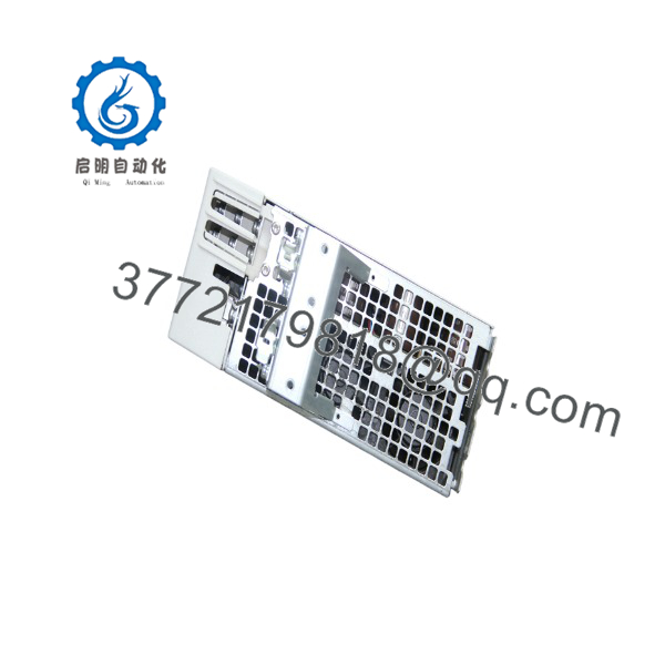
DKC02.3-040-7-FW
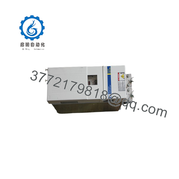
DKC02.3-040-7-FW
Quality Control & SOP Inspection Guidelines
Every DKC02 unit passes through our multi-stage Quality Control testing laboratory before dispatch to eliminate unboxing failures and ensure reliable field startup:
- Inbound Traceability & Visual Inspection:
- Serial number audit against OEM manufacturing database to catch counterfeit units.
- Inspection of heat sink fins for dust accumulation, physical corrosion, or mechanical impact damage.
- Audit of terminal connections, power blocks, optical fiber bays (X20/X21), and backplane latches.
- Electrical Isolation & Parameter Checks:
- 500 V DC Megger testing performed across main power terminals to earth ground (minimum target: > 10 M\Omega).
- Continuity check on internal soft-start charging circuit (60\ \Omega nominal) and internal bleeder resistors.
- Live Test Rack & Communication Handshake:
- Drive mounted to a standardized Rexroth EcoDrive test bench.
- +24 V DC control voltage applied; boot sequence monitored for abnormal current draw (> 19 W static draw triggers teardown).
- Fiber-optic SERCOS link established via ports X20/X21 with a motion master. H20 optical distortion LED verified for correct light level reception.
- Load Testing & Closed-Loop Motor Run:
- Paired with a genuine Indramat MKD servo motor.
- Executed 24-hour thermal cycle testing under full dynamic motion profiles at maximum rated peak currents (up to 40 A / 100 A depending on model rating).
- Thermal camera inspection during high-regen deceleration phases to monitor bleeder network heat dissipation.
- Final Firmware Documentation & ESD Packaging:
- Read and log exact firmware version string installed on the plug-in configuration module.
- Unit sealed inside anti-static (ESD) shielding bags and secured within high-density foam shipping containers. Test report generated and attached to shipping documentation.
Technical Pitfall & Field Survival Guide
❗ 1. Fiber-Optic Cable Handling & “H20” LED Warning:
SERCOS uses fiber-optic cables plugged into X20 (TX) and X21 (RX). The most common mistake during drive replacement is over-torquing, crimping, or exceeding the minimum bend radius of these fiber lines. If the drive displays a warning on the H20 LED, it indicates optical signal distortion or marginal light reception levels. Clean the fiber connector tips with isopropyl alcohol and verify optical power transmission levels before condemning a replacement drive.
❗ 2. Plugging/Unplugging the Firmware Configuration Module (FWA):
Never insert or remove the firmware module or parameter card while +24 V control power is active. Hot-swapping this card will corrupt the EEPROM or damage the internal processor board. Always isolate the drive from all AC main line feeds and +24 V control supplies, allowing 5 minutes for the DC-bus capacitors to discharge below 50 V DC, before swapping the card.
❗ 3. Matching Drive Peak Current Classes (016 vs. 040 vs. 100):
models share a identical housing profiles across different power levels (e.g., .3-040-7-FW vs. .3-100-7-FW). Do not rely on physical enclosure size to confirm replacement compatibility. Swapping a 40 A drive into a system tuned for a 100 A drive will cause immediate F226 (Overcurrent) or F219 (Braking Resistor Overload) trips under heavy mechanical acceleration profiles. Always match the exact ordering code string on the side nameplate.
❗ 4. Electrostatic Discharge (ESD) Shielding:
The signal connector pins and fiber optic transceivers are connected to sensitive internal CMOS logic. Handling the drive in high-humidity or cold panel environments without a grounded wrist strap can induce static discharge, damaging the internal optical receiver stage. Keep protective caps installed over X20/X21 ports until fiber cables are ready to seat.
Troubleshooting Quick Reference
| Symptom | Possible Cause | Relevance to | Quick Check Method | Recommendation |
| No 7-Segment Display / LEDs dark on boot | Missing +24 V DC control supply or blown internal fuse | ❌ Low | Measure voltage across +24 V and 0 V control terminals with a multimeter | Verify cabinet 24 V power supply unit output before replacing the drive module. |
F218 Fault Code |
Heatsink overtemperature shutdown | ✅ High | Check cabinet cooling fan function; clean heatsink cooling fins | Clear airflow blockages; if internal fan is seized, replace drive assembly. |
F219 Fault Code |
Bleeder / Braking resistor overheating | ✅ High | Check duty cycle and deceleration ramp rates in controller parameters | Extend deceleration ramp time or integrate an external braking resistor module. |
F226 Fault Code |
Overcurrent detected on motor output phase | ⚠️ Medium | Megger motor windings and check motor power cable for phase-to-phase shorts | If motor and cabling check out clear (> 50 M\Omega), internal IGBT power stage is shorted. Replace drive. |
| H20 LED illuminated solid | SERCOS optical power attenuation or dirty fiber connection | ✅ High | Check fiber optic cable bend radius and inspect fiber ends with optical power meter | Clean optical connectors or replace damaged SERCOS fiber cables. |
F434 / F234 Fault Code |
Emergency Stop circuit open or hardware enable missing | ❌ Low | Measure 24 V DC input at the drive hardware enable (E-Stop) terminal block | Trace external safety relay, door switches, and E-Stop circuit wiring. |
Note: If diagnostic codes persist after carrying out the checks above, export the error log using Indramat DriveTop software and contact our technical support team for detailed diagnostic review.
Frequently Asked Questions (FAQ)
Q: Can I replace a .3 drive with a different firmware version installed?
A: No, not directly without matching parameters. The drive hardware (.3 power stage) supports standard field replacements, but the operational parameters, motor profiles, and SERCOS communication parameters reside on the removable memory/firmware module (FWA). If you retain your original parameter module, transfer it to the replacement drive frame with power isolated. If the configuration card is corrupted, the new drive must be parameterized using Rexroth DriveTop software to match your exact axis mechanical ratios and motor feedback type.
Q: What is the difference between a DKC01, , and DKC03 drive?
A: The main distinction lies in the communication and control interface:
- DKC01: Uses analog voltage commands (\pm 10 V) or step/direction pulse interfaces.
- Uses digital SERCOS optical fiber interface (ports X20/X21) for synchronized multi-axis control.
- DKC03: Features integrated positioning control via PROFIBUS-DP or parallel discrete I/O interfaces.
Q: Is the drive hot-swappable while the DC bus is powered?
A: Absolutely not. Unplugging power connectors or fiber links while the 700 V DC bus is energized will cause electrical arcing, severe internal component damage, and potential injury. Always disconnect 3-phase AC input power and +24 V DC control power. Wait a minimum of 5 minutes for the internal capacitor bank (0.27 mF) to fully discharge below 50 V DC before servicing.
Q: Why are your New Surplus and Refurbished units significantly lower in cost than factory OEM list prices?
A: Legacy EcoDrive 03 components are no longer in active mass production by Bosch Rexroth. We source surplus units directly from decommissioned plants, panel builders’ overstock, and plant spare inventory liquidations. Every unit undergoes complete component-level testing, bus capacitor reforming, and full-load motor run tests in our lab to ensure performance meets original factory specifications before listing.
Q: What warranty comes with these replacement units?
A: All New Surplus and fully reconditioned drive controllers include a comprehensive 1-year replacement warranty. If a unit trips an internal fault during normal operating conditions within the warranty period, we supply an immediate exchange unit from stock to minimize your facility’s downtime.



