
 WhatsApp: +86 16626708626
 Email:
  Phone: +86 16626708626
Description
Key Technical Specifications
| Parameter | Value |
|---|---|
| Manufacturer | Bosch Rexroth / Indramat |
| Model | DKC03.3-040-7-FW |
| Product Family | EcoDrive 03 |
| Product Type | DKC servo drive controller |
| Series | 03 |
| Design Version | 3 |
| Rated Current | 40 A |
| Nominal DC Bus Voltage | 700 V DC |
| Permitted DC Bus Range | 500–800 V DC |
| Mains Input Voltage | 200–480 V AC |
| Mains Input Type | Three-phase |
| Mains Frequency | 50–60 Hz |
| Maximum Input Current | 16 A |
| Maximum Output Voltage | 800 V |
| Maximum Output Frequency | 1,000 Hz |
| Control Supply Voltage | 24 V DC |
| Control Power Consumption | Approximately 21 W |
| Power Dissipation, Continuous | Approximately 180 W |
| Communication | PROFIBUS-capable; confirm the installed optional interface card and firmware |
| Cooling Method | Internal blower cooling |
| Permitted Ambient Temperature | 0 to +45 °C at nominal ratings |
| Maximum Installation Altitude | 1,000 m above mean sea level at nominal ratings |
| Enclosure Rating | IP20 |
| Dimensions, H × W × D | 360 × 65 × 261 mm |
| Weight | Approximately 5.7 kg |
| Required Top Clearance | 150 mm |
| Required Bottom Clearance | 80 mm |
| Brake Supply Maximum Voltage | 40 V DC |
| Recommended Branch Protection | Verify against the complete cabinet design; one aftermarket reference states a 20 A branch-circuit fuse |
The DKC03.3-040-7-FW type code identifies a DKC EcoDrive 03 controller with Design Version 3, 40 A type current, 700 V DC-bus category, and firmware-dependent functionality. Bosch Rexroth’s EcoDrive 03 manual shows that the “FW” portion means firmware must be specified separately; the nameplate alone does not tell you the installed firmware package, motor data, or application parameters.
Public aftermarket references consistently report a 40 A rating, 700 V DC nominal bus, 200–480 V AC three-phase input, 24 V DC control supply, 0 to +45 °C operating range, 360 × 65 × 261 mm dimensions, and approximately 5.7 kg weight. Verify every installation-critical value against the unit nameplate and OEM project documentation.
Product Introduction
The Bosch Rexroth Indramat DKC03.3-040-7-FW is a 40 A EcoDrive 03 servo drive controller for closed-loop torque, speed, and position control in industrial machines. It operates from a 700 V DC link and supports three-phase 200–480 V AC supply systems through the applicable drive-power architecture. Typical installations include CNC equipment, packaging machinery, printing systems, material handling, and synchronized multi-axis production equipment.
This is a firmware-dependent drive, not a plug-and-play servo amplifier. The exact firmware, motor type, encoder feedback, parameter set, command interface, and optional communication hardware must match the existing installation. The “-7-FW” code points to the voltage class and firmware-required configuration; it does not prove that every DKC03.3-040-7-FW has the same fieldbus interface.
Troubleshooting Quick Reference
| Symptom | Possible Cause | Relevance to This Part | Quick Check Method | Recommendation |
|---|---|---|---|---|
| Drive display remains dark or no status LEDs appear | Missing 24 V DC control supply, blown control fuse, loose connector, failed internal control-power circuit | ✅ High | Measure 24 V DC directly at the drive control-supply terminals using a CAT-rated meter. Confirm polarity, upstream fuse condition, and supply voltage under load. | Check the 24 V DC supply and wiring before replacing the drive. A healthy DC bus does not guarantee that the control electronics have power. |
| Drive will not enable but display is active | Missing enable signal, active external safety chain, emergency stop open, controller inhibit, parameter or firmware mismatch | ⚠️ Medium | Review drive diagnostic code, controller enable command, safety-chain contacts, and the 24 V DC enable circuit. Compare status with the machine electrical drawing. | Do not replace the drive first. Most “won’t enable” faults originate in safety wiring, PLC logic, or missing enable conditions. |
| DC bus undervoltage or mains fault appears | Incoming phase loss, weak supply, line fuse issue, failed contactor, loose mains terminal, incorrect incoming voltage | ❌ Usually low | With safe procedures and qualified personnel, measure phase-to-phase voltage upstream and downstream of the main contactor. Inspect line fuses and contactor contacts. | Correct the incoming supply issue. The drive expects a system compatible with its 200–480 V AC input range and 700 V DC nominal bus architecture. |
| Motor hums or locks but does not rotate | Incorrect motor cable, encoder feedback fault, mechanical jam, brake not releasing, wrong motor parameters | ⚠️ Medium | Isolate power. Check motor shaft movement, brake supply, motor cable continuity, encoder connector seating, and installed motor data. | Verify motor and encoder part numbers against the original drive parameter set before condemning the controller. |
| Axis runs away, moves in the wrong direction, or faults on motion | Incorrect feedback polarity, wrong motor data, parameter loss, incorrect command scaling, encoder problem | ✅ Medium | Stop the machine safely. Compare the replacement drive’s parameters with a known-good backup and verify motor-feedback wiring. Run only controlled commissioning moves. | Restore the approved parameter set. Never “tune by trial” on a production axis without travel limits and a controlled setup. |
| PROFIBUS communication fault | Incorrect address, damaged bus cable, terminator setting error, missing or wrong option card, PLC configuration mismatch | ⚠️ Medium | Check bus connector power, shield continuity, terminating resistors at the two physical ends, node address, and PLC diagnostics. Inspect the actual interface card. | Confirm the installed DKC communication option and firmware. Do not assume PROFIBUS is standard on every DKC03.3-040-7-FW. |
| Drive overheats or trips after several minutes | Blocked airflow, failed internal blower, insufficient cabinet clearance, excessive motor load, high ambient temperature | ✅ High | Inspect fan operation and cabinet filters. Confirm 150 mm clearance above and 80 mm below the drive. Measure motor current during the fault cycle. | Clean airflow paths, repair the fan system, and verify load sizing. The documented nominal ambient limit is 0 to +45 °C. |
| Repeated overcurrent fault during acceleration | Mechanical binding, excessive acceleration setting, shorted motor cable, motor winding fault, incorrect current limits | ⚠️ Medium | Disconnect and insulation-test the motor cable and motor only using procedures approved for the motor and drive system. Compare commanded acceleration and actual load. | Check mechanics and motor cable first. Do not repeatedly reset an overcurrent fault; that can damage the drive or motor. |
| Replacement drive shows different fault behavior | Firmware mismatch, missing parameter set, different interface hardware, changed motor data, wrong power section | ✅ High | Record the old drive’s full nameplate, firmware card, installed option cards, and parameters before removal. Compare all hardware and software identifiers. | Order against the complete drive configuration, not only DKC03.3-040-7-FW. Request firmware and interface details before shipment. |
| Drive trips immediately after installation | Incorrect mains/DC-bus wiring, phase wiring error, wrong control connector, damaged motor cable, ESD or installation damage | ✅ High | De-energize, lock out, and inspect all power and control connections against the OEM wiring diagram. Check connector keying and terminal torque. | Do not reapply power until the wiring is verified by a qualified drive technician. This unit operates at hazardous DC-bus voltage. |
❗ High-voltage warning: This drive uses a DC link in the 500–800 V DC range, with a nominal 700 V DC bus. Stored energy remains after supply removal. Follow the Bosch Rexroth discharge-time requirement in the applicable documentation, verify the DC bus is at a safe voltage with an approved meter, and follow site lockout/tagout before touching power terminals.
❗ Firmware warning: I have seen a drive replacement turn into a two-day outage because the spare looked identical but contained a different firmware package and no usable parameter backup. Before removing the old unit, record every nameplate field, interface card, firmware label, motor model, encoder type, bus address, and parameter version. Back up the commissioning data if the system permits it.
If the failure remains unclear, send technical support a photo of the entire nameplate, drive fault code, motor nameplate, interface cards, controller diagnostic log, parameter backup, and voltage readings from the mains, DC bus, and 24 V DC control supply.
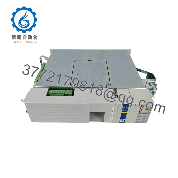
DKC03.3-040-7-FW
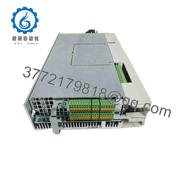
DKC03.3-040-7-FW
Frequently Asked Questions
What is the Bosch Rexroth Indramat .3-040-7-FW?
The .3-040-7-FW is an Indramat EcoDrive 03 servo drive controller manufactured under the Bosch Rexroth product family. It controls compatible servo motors in closed-loop position, speed, and torque applications. Its rated current is 40 A and its nominal DC-bus voltage class is 700 V DC.
What does the “040” in .3-040-7-FW mean?
The “040” identifies the 40 A type-current rating. The EcoDrive 03 instruction manual lists 040 and 100 as current-code options for this DKC controller family. Do not confuse the 40 A drive-current class with the upstream line current, motor continuous current, or required fuse size.
What does the “7-FW” suffix mean?
The “7” identifies the 700 V DC-bus voltage category. “FW” means that firmware defines the drive’s functional capability and must be specified separately. That is the crucial detail: the base model number does not identify the exact firmware package, application function, motor compatibility, or installed communication interface.
Does every .3-040-7-FW include PROFIBUS?
No. Treat PROFIBUS as configuration-dependent until you inspect the actual drive. Some aftermarket sources list PROFIBUS capability or a PROFIBUS option card for this model, while the Bosch Rexroth type-code documentation makes clear that firmware is separately specified. Confirm the physical communication card, connector type, bus address hardware, and installed firmware before ordering.
Can I replace my failed drive with any .3-040-7-FW?
Not safely without verification. Match the full nameplate, 40 A current class, 700 V bus category, firmware, installed option cards, encoder and motor feedback type, motor model, brake requirements, control wiring, and parameter set. A physically matching DKC can still fail to commission if the firmware or parameter configuration differs.
Will replacing this drive erase machine parameters?
The machine PLC program will normally remain intact, but the drive-specific motor and application parameters may not transfer automatically. Some installations store parameters in the controller or external commissioning software; others depend on the existing drive configuration. Back up parameters before removal. If the old drive is dead, obtain an archived parameter file or read the data from a matching commissioned axis.
Can I hot-swap the .3-040-7-FW?
No. Do not hot-swap this drive. It carries hazardous mains and DC-bus energy, and removal may damage power connectors, cause uncontrolled machine behavior, or create a serious shock and arc-flash hazard. Shut down under lockout/tagout, allow the bus to discharge according to OEM documentation, verify voltage, and use qualified personnel.
Is .3-040-7-FW obsolete?
It is a legacy EcoDrive 03 product and should be sourced as surplus, refurbished, or repair-stock inventory. Bosch Rexroth legacy support status, repair availability, and replacement strategy should be confirmed for the exact hardware and firmware configuration before a shutdown-critical purchase. Aftermarket sources continue to list the model, but listing availability does not equal factory manufacture or long-term support.
Why is a New Surplus .3-040-7-FW less expensive than a current-production servo drive?
New Surplus units typically come from unused OEM spares, machine-builder inventory, discontinued projects, distributor overstock, or decommissioned equipment. The price reflects product age and inventory liquidity. For a critical motion axis, insist on exact-unit photos, complete nameplate verification, firmware and option-card photos, capacitor condition or reforming history if applicable, functional test evidence, written warranty, and clear return terms.
What test evidence should I request before buying a refurbished unit?
Request documented inbound inspection; photos of the nameplate, connectors, and interface cards; controlled power-up; 24 V DC control-supply verification; blower operation; DC-bus and fault-monitoring checks; a compatible motor run test under controlled load; encoder-feedback verification; communication testing for the installed option card; and a recorded fault-free run period. For a high-voltage legacy drive, a supplier should also confirm ESD-safe handling, connector condition, and safe packaging. Bench testing does not replace final commissioning with the correct motor, parameter file, safety circuit, and machine mechanics.



