
 WhatsApp: +86 16626708626
 Email:
  Phone: +86 16626708626
Description
Key Technical Specifications
| Parameter | Technical Specification |
| Manufacturer | Bosch Rexroth / Indramat |
| Part Number / Type Code | DKC11.1-040-7-FW |
| Product Family | EcoDrive DKC Series |
| Interface Option | Analog Interface (±10V) / Stepper Pulse Interface (Series 11) |
| Design Version | Version 1 |
| Rated Current Output | 40 A |
| DC-Bus Nominal Voltage | 700 VDC |
| Control Voltage Input | 24 VDC (±15%) |
| Output Voltage Range | 3-Phase 0–800 VAC |
| Motor Compatibility | Indramat MKD, MHD, and MKE synchronous AC servo motors |
| Protection Rating | IP20 |
| Operating Temperature | 0 °C to +45 °C (up to +55 °C with derating) |
| Physical Dimensions | 360 mm (H) x 85 mm (W) x 261 mm (D) |
| Weight | 6.5 kg (14.3 lbs) |
Product Introduction & Supply Chain Strategy
The Bosch Rexroth Indramat DKC11.1-040-7-FW is a 40 A digital AC servo drive controller operating on a 700 VDC bus architecture. Equipped with a standard analog/stepper interface, this EcoDrive controller processes ±10V speed/torque commands or pulse-direction positioning signals for Indramat MKD and MHD servo motors in automated assembly, packaging, and material handling systems.
Because Bosch Rexroth has declared the EcoDrive 01/11 series obsolete, securing this module as New Surplus ensures continuous plant operations without incurring the heavy capital expense of a full motion control retrofit. Sourcing factory-unused surplus eliminates the premature failure risks associated with degraded capacitors and thermal fatigue found in second-hand equipment. Maintaining 1-2 units on-site safeguards your Total Cost of Ownership (TCO) by eliminating unplanned downtime during emergency outages.
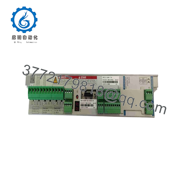
DKC11.1-040-7-FW
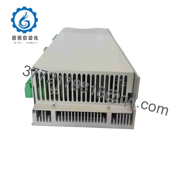
DKC11.1-040-7-FW
Installation & Configuration Guide
Stage 1: Pre-Installation (Prep & Safety)
- Perform Lock-Out/Tag-Out (LOTO) on the main 3-phase line power, 24 VDC logic power, and external DC bus connections.
- Put on a grounded ESD wrist strap before handling terminal connectors, signal wiring, or firmware modules.
- Record all analog input shield groundings, signal pinouts, and the positions of any onboard address or configuration switches on the existing drive.
Stage 2: Removal
- Wait at least 5 minutes after switching off power to allow the 700 VDC bus capacitors to discharge below 50 VDC.
- Disconnect the analog/digital I/O terminal connectors, 24 VDC logic power plug, motor power output, and encoder feedback cable.
- Unbolt the top and bottom mounting screws from the enclosure backplate and pull the drive straight out.
Stage 3: Installation (Clone & Seat)
- Inspect the rear heat sink fins and connector pins on the new surplus DKC11.1-040-7-FW unit for physical integrity.
- Transfer the existing plug-in firmware module (FWA/GSM card) from the old drive into the top firmware slot of the replacement unit.
- Replicate any DIP switch or jumper configurations from the original drive onto the replacement unit.
- Mount the drive securely against the cabinet backplate, ensuring solid metal-to-metal contact for earthing and thermal dissipation.
Stage 4: Power-On & Testing
- Apply 24 VDC control power prior to energizing main AC power.
- Verify that the 2-digit, 7-segment display shows
bb(Ready for Operation). - Enable main line power to charge the 700 VDC bus.
- Apply a low-voltage analog command (e.g., +1V) to test smooth motor rotation and verify encoder feedback scaling in the controller.
Firmware/Software Versions & Upgrade Notes
- Firmware Card Requirement: The
-FWdesignation indicates that the unit operates via an external, removable plug-in firmware card (FWA card). - Firmware Portability: Swap the existing FWA card directly into the new surplus DKC11.1-040-7-FW unit. This transfers all calibrated motor parameters, analog scaling factors, and fault limits automatically.
- Compatibility Notes: The DKC11.1 hardware design is specific to analog and stepper signal processing. Do not attempt to insert firmware cards designed for SERCOS (DKC02/DKC12) or PROFIBUS (DKC03/DKC13) units into a DKC11.1 hardware base.
Frequently Asked Questions (FAQ)
Is this Indramat .1-040-7-FW drive brand new or refurbished?
This unit is strictly New Surplus (Original Unused stock). It has never been installed on a machine, pulled from a decommissioned plant, or subjected to board-level repairs.
What does the “.1” series designation mean compared to “DKC02.3”?
The .1 series features an analog (±10V) and stepper pulse interface (Series 11), whereas the DKC02 series uses a optical SERCOS digital bus interface (Series 02). They are designed for different control architecture inputs and are not directly interchangeable without changing the master controller interface.
Why does the model number end in “-FW”?
The -FW suffix stands for “Firmware.” It denotes that the physical drive controller is supplied without fixed internal firmware; operational firmware is supplied via a plug-in FWA card inserted into the top of the unit.
Can I replace a .1-040-7-FW with a higher current drive like a .1-100-7-FW?
While a 100 A drive can physically handle the current requirements, changing drive power sizes alters internal current loop parameters and fuse ratings. It is recommended to use the exact 40 A rating (040) for drop-in replacement.
What warranty is provided with this New Surplus drive?
All New Surplus Indramat .1-040-7-FW drive controllers include a 1-year functional warranty from the date of purchase.



