
 WhatsApp: +86 16626708626
 Email:
 Phone: +86 16626708626
Description
Key Technical Specifications
| Parameter | Value |
|---|---|
| Manufacturer | Bosch Rexroth AG (Indramat product line) |
| Material Number | R911308684 |
| Series / Type | MSK030, IndraDyn S synchronous servo motor |
| Size / Torque Class | 030C (medium rotor inertia, 4 Nm peak torque) |
| Nominal Speed | 9000 rpm (type code “0900”) |
| Standstill Torque (continuous) | approx. 0.9 Nm (natural convection) |
| Peak Torque | up to 4 Nm |
| Torque Constant | approx. 0.58 Nm/A |
| Encoder (code “M1”) | Optical IndraDyn S encoder, EnDat interface, 128 signal periods, multiturn-capable design |
| Holding Brake (code “UG1”) | Electrically releasing holding brake, 1 Nm, plain shaft (no keyway, shaft seal ring included) |
| Cooling | Natural convection (no fan, no liquid cooling) |
| Degree of Protection | IP65 |
| Insulation Class | F (per DIN EN 60034-1) |
| Connector | Rotatable motor/encoder connectors (240° orientation) |
| Feedback Cable | IndraDyn S EnDat-compatible encoder cable |
| Drive Compatibility | IndraDrive Cs/HMI, EcoDrive, HMV/DDS-family legacy drives via EnDat 01 interface |
| Ambient Temperature | 0 to +40 °C (rated operation) |
| Mounting | Flange per standard MSK 030 frame, run-out class “N” |
⚠️ Verify precise electrical limits (rated current, winding code) against the official Rexroth datasheet for R911308684 before installation. Standstill torque values vary with cooling condition and duty cycle — the figures above reflect natural convection ratings.
Product Introduction
The Bosch Rexroth MSK030C-0900-NN-M1-UG1-NNNN (R911308684) is an IndraDyn S synchronous AC servo motor in the compact MSK 030 frame, built for high-dynamic positioning axes in packaging machines, machine tools, robotics, and general motion applications. It pairs a 9000 rpm rotor with an optical EnDat-class encoder delivering 128 signal periods, which keeps positioning resolution and repeatability tight even on multi-turn axes.
The UG1 option adds a 1 Nm electrically releasing holding brake and a plain shaft with seal ring — the standard configuration integrators choose for vertical axes and geared servo applications. Motor connectors rotate 240°, so cable routing works in tight cabinets and cramped machine frames. IP65 sealing means the motor survives washdown-adjacent environments without an added enclosure. R911308684 runs on Rexroth IndraDrive and legacy Indramat drive platforms that support the EnDat 01 encoder interface — verify drive firmware support before ordering if your drive predates 2005.
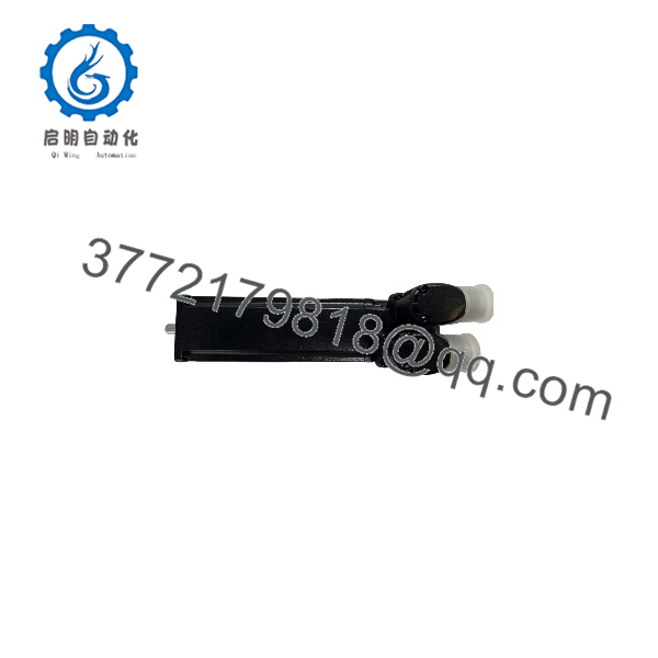
MSK030C-0900-NN-M1-UG1-NNNN
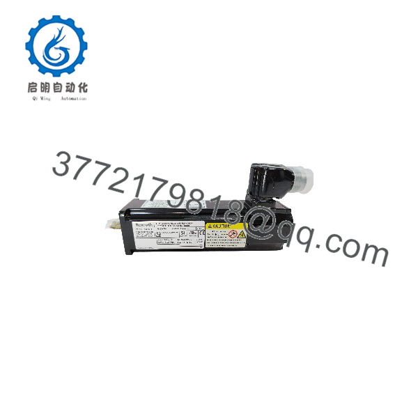
MSK030C-0900-NN-M1-UG1-NNNN
Installation & Configuration Guide
Total estimated time for a competent technician: 30–45 minutes, plus drive commissioning.
Stage 1: Pre-Installation Preparation (10 min)
⚠️ Safety First: Notify operations of planned axis downtime. Move the axis to a safe position, engage mechanical locks if the axis is vertical (the 1 Nm holding brake is a functional brake, not a personnel-safety device). Lock out/tag out drive power. Wait 5 minutes for DC bus and encoder electronics to discharge.
Tools Required:
- Grounded ESD wrist strap
- Hex key set (MSK connector housings) and torque wrench
- Multimeter
- Label tape and wire labels
- Smartphone — take photos of everything before you disconnect anything
Data Backup:
- Photograph the motor nameplate and both connector orientations.
- In the drive commissioning tool (Bosch Rexroth IndraWorks / DriveTop or the legacy HMI), back up the current motor parameter set (MOT-xx objects) and fault log.
- Record the encoder part number from the old motor — the encoder interface must match (EnDat 01 vs EnDat 02 are not interchangeable).
- If the drive holds the axis in position, note the current position value so you can re-home with minimal error.
Stage 2: Removing the Old Motor (5–10 min)
- Disconnect the motor power connector (2-finger twist-release on the MSK series) and the encoder connector. Label both cables.
- Support the motor before removing flange bolts — MSK 030 units weigh roughly 3–4 kg depending on brake option, and a falling motor damages the shaft and connector.
- For geared applications: mark the coupling alignment before separating. Misaligned reassembly destroys shaft seals within weeks.
- Remove the four flange bolts and withdraw the motor straight back — do not pry against the shaft.
- Inspect the mounting flange and coupling for wear, misalignment, or metal dust (a symptom of bearing failure that will kill the replacement too).
⚠️ Note: Keep the old motor on the bench until the new one runs a full cycle without fault. Nameplate comparison between old and new units takes 60 seconds and catches 90% of ordering errors.
Stage 3: Installing the New Motor (10 min)
- Ground yourself. ESD damage to the encoder board is the most common way a new MSK motor dies before first power-up.
- Verify the nameplate matches exactly: MSK030C-0900-NN-M1-UG1-NNNN and R911308684. The “C” inertia class, “0900” speed code, “M1” encoder, and “UG1” brake/shaft code all matter. A “B” inertia or “H1” Hiperface encoder version will not run correctly on your existing parameter set.
- Mount the motor to the flange; torque the four bolts to the value in the MSK 030 datasheet. Align the coupling within the manufacturer’s tolerance — use a dial indicator, not your eye.
- Connect the motor power cable and encoder cable. Rotate connector housings to match your cable routing; hand-tight only — the MSK connectors seal with light torque, and over-tightening cracks the housings.
- Torque all fasteners per the mounting drawing.
Self-Checklist:
- Nameplate matches R911308684 exactly
- Coupling alignment checked with indicator
- Both connectors seated and locked
- Brake wiring connected (UG1 brake requires its own supply per drive wiring diagram)
Stage 4: Power-Up & Testing (10–15 min)
Pre-Power Check:
- Megger/continuity check the motor phases U/V/W for phase-to-phase balance and phase-to-ground insulation (>10 MΩ at 500 V DC — disconnect the drive first; never megger into drive power electronics).
- Verify encoder cable shielding is clamped at both ends.
Power-On Steps:
- Apply control power first (drive logic), before enabling power electronics.
- Power the drive and check for encoder communication faults. An EnDat communication error at this stage usually means a wrong cable or a damaged encoder connector — power down before re-seating.
- Clear the fault log, then load the backed-up motor parameter set. Confirm MOT-xx parameters match the new nameplate (winding data is stored in the motor’s digital parameter memory, but the drive must read it correctly).
- Brake test: Enable the drive and manually command the brake to release. Confirm the brake releases and re-engages cleanly before jogging.
- Jog the axis at low speed in both directions. Check for vibration, hunting, or unusual acoustic noise — these indicate coupling misalignment or wrong inertia class.
- Re-home the axis and run one full production cycle at reduced speed before releasing to production.
⚠️ Troubleshooting Note: F3189/F3190-class encoder faults (communication) point to the encoder cable or connector seating. If the drive reports a motor data mismatch after parameter load, the replacement motor may be a different winding/inertia variant — stop and compare nameplates before enabling torque. A motor that runs but hums hot at standstill after 10 minutes indicates brake drag: check the brake supply voltage (brake coil undervoltage keeps the brake partially engaged).
Frequently Asked Questions (FAQ)
Q1: Can I hot-swap this motor with the drive powered up?
No. The MSK encoder interface and the drive power stage will not tolerate live disconnection. Pulling the encoder connector under power can damage the encoder board in the motor and the feedback channel in the drive — I’ve seen both die from one careless swap. Kill the drive power, confirm the DC bus is discharged (5 minutes minimum on IndraDrive Cs), then disconnect. Also note the UG1 brake: with power removed and the brake released by the drive’s brake control, a vertical axis will drop. Secure the load mechanically first.
Q2: Is the MSK030C still a current product, and is this unit genuinely new?
The MSK series remains an active Bosch Rexroth product line, though older material numbers like R911308684 are increasingly supplied through surplus channels as production batches age. Our stock is New Original / New Surplus: factory packaging, unbroken seal where applicable, nameplate and digital parameter memory intact, and verified against the OEM datasheet. If the unit has ever been powered, we tell you and sell it as tested refurbished at a lower price — we don’t blur the two. Test photos and the functional test report are available on request.
Q3: What can I substitute if R911308684 is out of stock?
The nearest functional equivalents within MSK 030 are variants that preserve the “0900” speed code and “M1” optical encoder — for example, MSK030C-0900 with a different shaft/brake option code (e.g., a keyway version requiring a new hub) or the MSK030B inertia class if your application tolerates lower rotor inertia mismatch. Do not substitute an H1 (Hiperface, 16 signal periods) encoder version — your drive parameters and position resolution will not match without re-commissioning. If you’re unsure, send us your drive type and we’ll tell you honestly whether a swap works or whether you need the exact material number.
Q4: Will I lose my program or position data when I swap the motor?
Your drive program stays in the drive — pulling the motor doesn’t touch it. What you lose is the motor’s stored digital type plate data (motor-identity parameters), which the drive reads from the new motor automatically on power-up. The real risk is the axis home position: the new motor’s zero reference will differ from the old one by a small angle, so re-home the axis after the swap. Budget 15 minutes for homing plus one validation cycle. Back up your drive parameters before starting anything regardless — that takes 2 minutes and has saved me more weekends than I can count.
Q5: What does the “UG1” holding brake actually do, and can I rely on it?
The 1 Nm holding brake is an electrically releasing friction brake that holds the shaft when the drive is disabled. It’s designed for gravity-load holding and positioning accuracy — vertical axes, tool spindles, z-axes. It is not a safety-rated brake for personnel protection; that requires a safe-hold variant (SBM/SMB options) and a proper safety assessment under ISO 13849. For a 0.9 Nm-class motor, 1 Nm of holding torque covers the motor’s own rated output, but if your gearbox multiplies a hanging load back through the shaft, do the math before trusting it.
Q6: Why is your price below the Rexroth factory list price?
Because surplus-channel stock doesn’t carry the OEM’s distribution markup, engineering-support overhead, or fresh-production lead time. The motor is the same factory-built unit; what you give up is OEM warranty processing (we carry the 1-year warranty ourselves) and long lead-time guarantees. On a dead production axis, trading a 12-week factory lead time for 3-day shipping from tested stock is usually an easy call. On a new machine build, buying through the OEM channel sometimes still makes sense for warranty consolidation — we’ll tell you which situation you’re in if you ask.
Q7: Do you test the motor before it ships?
Every unit gets a live functional test: power-up, encoder communication check against a Rexroth IndraDrive test bench, phase-to-phase and phase-to-ground insulation measurement (500 V Megger, >10 MΩ), brake release/engage verification, and a thermal-stable continuous run. The encoder angle count, brake current draw, and insulation values are recorded on a test report that ships documentation is available on request. We won’t claim a motor is “100% failure-proof” — no honest engineer would. What we will claim: verified fully functional under load testing before it leaves our bench.



