WhatsApp: +86 16626708626
 Email:
 Phone: +86 16626708626
Description
Key Technical Specifications
| Parameter | Value |
|---|---|
| Manufacturer | Bosch Rexroth AG (Indramat product line) |
| Material Number | R911309706 |
| Series / Type | MSK050, IndraDyn S synchronous servo motor |
| Frame Size / Length | 050 / length C |
| Winding Code | 0300 |
| Rated Speed | 4700 rpm |
| Standstill Torque (continuous, 100 K) | 5.5 Nm (natural convection) |
| Peak Torque | 15.0 Nm |
| Continuous Current at Standstill | approx. 3.4 A |
| Maximum Current | 12.4 A |
| Winding Resistance (20 °C) | 6.60 Ω |
| Winding Inductivity | 46.1 mH |
| Voltage Constant | 109.0 V / 1000 min⁻¹ |
| Torque Constant | approx. 1.62 Nm/A |
| Rotor Inertia | 0.00033 kg·m² |
| Encoder (code “M1”) | Optical multiturn absolute encoder, EnDat interface, 128 signal periods |
| Holding Brake (code “UG1”) | Electrically releasing holding brake, 6 Nm, plain shaft with seal ring |
| Cooling | Natural convection |
| Degree of Protection | IP65 |
| Insulation Class | F (per DIN EN 60034-1) |
| Thermal Time Constant (winding) | 14 min |
| Ambient Temperature | 0 to +40 °C |
| Max Permissible Axial Force | 300 N |
| Sound Pressure Level | approx. 75 dB(A) |
| Mounting | Flange per standard MSK 050 frame, run-out class “N”, connectors rotatable 240° |
⚠️ Verify precise electrical limits and brake release voltage against the official Rexroth datasheet for R911309706 before installation. Torque figures assume natural convection at 100 K winding temperature rise; ratings shift with ambient temperature and duty cycle.
Product Introduction
The Bosch Rexroth MSK050C-0300-NN-M1-UG1-NNNN (R911309706) is an IndraDyn S synchronous AC servo motor in the MSK 050 frame, length C — the workhorse size for packaging lines, assembly machines, robot tooling axes, and general motion applications needing more than the 030 frame can deliver. The 0300 winding supports 4700 rpm rated speed with 5.5 Nm continuous torque and 15 Nm peak, which covers most high-cycling handling axes with real overload headroom for acceleration.
The M1 encoder is an optical multiturn absolute unit with 128 signal periods, so the axis retains absolute position through power cycles without a homing routine after every restart. The UG1 option adds a 6 Nm electrically releasing holding brake on a plain shaft — enough to hold a geared vertical axis. Rotor inertia sits at 0.00033 kg·m², giving strong dynamic response for its torque class. The motor runs on Rexroth IndraDrive and legacy Indramat drive platforms with EnDat 01 encoder support — confirm your drive firmware supports the M1 multiturn encoder before ordering, especially on pre-2005 EcoDrive and HDS hardware.
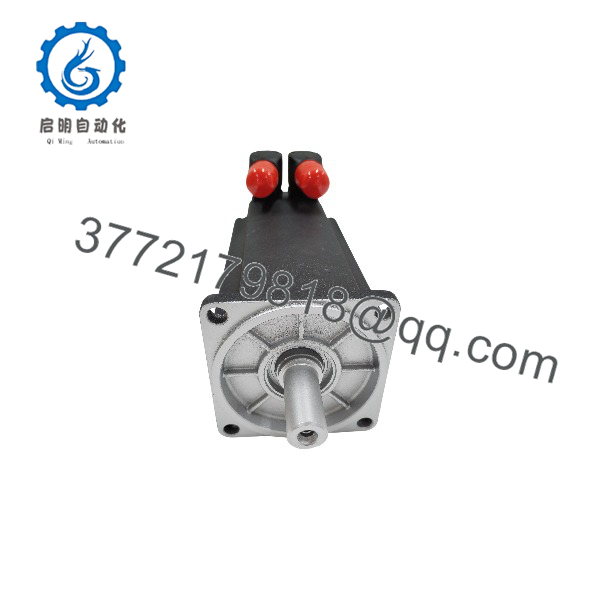
MSK050C-0300-NN-M1-UG1-NNNN
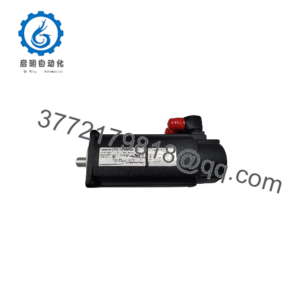
MSK050C-0300-NN-M1-UG1-NNNN
Installation & Configuration Guide
Total estimated time for a competent technician: 40–60 minutes, plus drive commissioning and homing.
Stage 1: Pre-Installation Preparation (10–15 min)
⚠️ Safety First: Notify operations of planned axis downtime. Move the axis to a safe position. On vertical or gravity-loaded axes, engage a mechanical support before touching anything — the 6 Nm holding brake is a functional brake, not a personnel-safety device, and it will release when you disconnect the motor. Lock out/tag out drive power and wait 5 minutes for the DC bus to discharge.
Tools Required:
- Grounded ESD wrist strap
- Hex key set for MSK connector housings, torque wrench for flange bolts
- Multimeter and 500 V insulation tester
- Label tape and wire labels
- Smartphone — photograph everything before disconnecting
Data Backup:
- Photograph the old motor’s nameplate and both connector orientations.
- In IndraWorks / DriveTop (or the legacy HMI), back up the motor parameter set and the fault log.
- Record the axis home offset and current position value — the new encoder’s multiturn reference will differ, and you’ll want the old numbers for comparison after re-homing.
- Confirm the encoder cable type. The M1 EnDat multiturn encoder requires a full EnDat cable with battery backup wiring for the multiturn memory; a stripped-back or wrong-pinout cable produces intermittent position loss that will drive you crazy at 2 AM.
Stage 2: Removing the Old Motor (10 min)
- Secure the load mechanically. Disconnect the motor power connector and encoder connector. Label both cables at both ends.
- Support the motor before removing flange bolts — an MSK 050 with brake weighs roughly 5–7 kg, and dropping one bends the shaft and cracks the encoder housing.
- Mark coupling alignment on geared setups. I reuse this note on every motor job because it keeps biting people: a misaligned reassembly eats the shaft seal and bearing within weeks, and you get to do this swap twice.
- Remove the four flange bolts and withdraw the motor straight back. Never pry against the shaft.
- Inspect the flange face, coupling, and any metal dust. Fine gray residue means bearing failure — find the root cause or the replacement motor inherits it.
⚠️ Note: Keep the old motor on the bench until the new one runs a full production cycle. Compare nameplates side by side; the 050 frame comes in A, B, C, and D lengths with different stack lengths and torque ratings, and “MSK050” alone is not a match.
Stage 3: Installing the New Motor (15 min)
- Ground yourself first. ESD to the encoder board is the most common cause of a dead-on-arrival MSK motor.
- Verify the nameplate matches exactly: MSK050C-0300-NN-M1-UG1-NNNN, material number R911309706. Every code segment matters — length “C”, winding “0300”, encoder “M1”, brake/shaft “UG1”. A “B” or “D” length changes torque and stack dimensions; an “H1” Hiperface encoder will not talk to a drive configured for EnDat.
- Mount to the flange; torque the bolts per the MSK 050 mounting drawing. Dial-indicate the coupling — eye-balling it is not alignment.
- Connect power and encoder cables. Rotate connector housings for routing; hand-tight only. Over-torquing MSK connector housings cracks them.
- Brake wiring: the UG1 brake takes its own 24 V supply (typically switched by the drive’s brake control output). Verify the brake release voltage spec on the datasheet — an undervolted brake stays partially engaged, drags, and cooks the motor from the inside.
Self-Checklist:
- Nameplate matches R911309706 exactly
- Coupling alignment verified with indicator
- Encoder cable is full EnDat pinout with battery wire
- Brake supply wired to drive-controlled output
- Both connectors seated and locked
Stage 4: Power-Up & Testing (15–20 min)
Pre-Power Check:
- Measure phase-to-phase resistance on U/V/W — expect roughly 6.6 Ω per the winding data, balanced within a few percent.
- Insulation test phase-to-ground at 500 V DC, >10 MΩ. Disconnect the drive power stage first — never megger into drive electronics.
- Verify encoder shield clamping at both the motor and drive ends.
Power-On Steps:
- Apply control power to the drive before enabling power electronics.
- Power up and check for encoder communication faults. An EnDat comms error here is almost always cable pinout or connector seating — power down fully before re-seating.
- Confirm the drive reads the new motor’s digital type plate. IndraDrive reads motor identity automatically; if it reports a motor data mismatch, stop and compare nameplates.
- Brake test: enable the drive, command brake release, and listen. You should hear a clean clack — release and re-engage. A buzz or drag means supply voltage problems.
- Jog at low speed in both directions. Watch for vibration or hunting — with a 0.00033 kg·m² rotor, inertia mismatch against a large load shows up as audible hunting immediately.
- Re-home the axis, run one cycle at reduced speed, then verify position repeatability on the multiturn encoder before releasing the machine to production.
⚠️ Troubleshooting Note: Encoder comms faults (F3189-class on IndraDrive) point to cable or connector; a motor-data mismatch fault points to a wrong variant ordered; a motor that runs rough and trips on overcurrent at moderate speed usually means the peak current limit in the drive is set below the application’s acceleration demand — 12.4 A is available if the drive is configured for it.
Frequently Asked Questions (FAQ)
Q1: Can I hot-swap this motor with the drive powered up?
No, and this one is worse than the small frames. Disconnecting the M1 encoder under power can damage the encoder board in the motor and the feedback channel in the drive. And the 6 Nm brake: with brake power removed and the drive disabled, a vertical axis drops the moment you break the mechanical connection. I’ve watched a 40 kg gripper assembly ride a z-axis to the floor because someone skipped the mechanical support. Full LOTO, 5-minute bus discharge, secure the load. No exceptions.
Q2: Is the MSK050C still supported, and is this unit genuinely new?
The MSK series is an active Bosch Rexroth line, but older material numbers like R911309706 increasingly ship from surplus stock rather than fresh production batches. Our stock is New Original / New Surplus: factory packaging, intact nameplate and digital parameter memory, verified against the OEM datasheet. If a unit has ever been powered, we sell it as tested refurbished at a lower price and say so plainly. Test photos and the functional test report are available on request — ask, we’d rather show you than have you take our word for it.
Q3: What are my substitution options if R911309706 is out of stock?
Within MSK 050, the closest equivalents keep the “0300” winding and “M1” encoder — for example, the UG0 plain-shaft version if your axis doesn’t need a brake, or a keyway variant if you can change the hub. Do not substitute a different winding code without checking the drive’s current limits and voltage constant, and never swap the M1 (EnDat) encoder for an H1 (Hiperface) version — the drive will not communicate with it without full re-commissioning. If you’re between options, send us your drive type and axis load; we’ll tell you honestly whether a variant swap works or whether you need the exact material number.
Q4: Will I lose my program or position data when I swap the motor?
The drive program is untouched. The complication is position: the M1 encoder is multiturn absolute, so after the swap the axis position reads from the new motor’s encoder, and its reference will differ slightly from the old motor’s. Re-home once, record the offset, and the axis is back. One detail that trips people: the multiturn memory is battery-backed through the encoder cable. If the battery circuit in your cable or drive is dead, the axis loses absolute position on every power cycle — if that’s happening on the old motor, fix the battery path before blaming the new motor.
Q5: How much load can the 6 Nm holding brake actually hold?
6 Nm at the motor shaft, friction-based, with the drive disabled. Direct-drive, that holds about 6 Nm of static load. Through a gearbox, it depends on ratio and efficiency — a 10:1 planetary with 90% efficiency gives you roughly 50 Nm of holding torque at the output, minus a safety factor for wear. Like all functional brakes, its holding force decays over life with pad wear. It is not a safety-rated brake for personnel protection; that requires a safe-hold option (SBM/SMB) and a PL/SIL assessment per ISO 13849. If your axis holds a load over people, that’s a different motor option — tell us and we’ll quote it.
Q6: Why is your price below the Rexroth factory list price?
Surplus-channel stock doesn’t carry fresh-production lead time, OEM distribution markup, or engineering-support overhead. Same factory-built motor; the trade is that we carry the 1-year warranty ourselves instead of the OEM. On a down production axis, 3-day shipping from tested stock versus an 8–12 week factory lead time is usually the whole conversation. For new machine builds where you want consolidated OEM warranty across the whole line, the factory channel can still make sense — we’ll tell you when it does.
Q7: Do you test the motor before it ships?
Every unit gets a live functional test: power-up, encoder communication check against a Rexroth IndraDrive test bench, phase-to-phase resistance balance, 500 V insulation test (>10 MΩ), brake release/engage verification at rated voltage, and a continuous run to thermal stability. Results are recorded on a test report available on request. We won’t claim any motor is “100% failure-proof” — no honest engineer would. What we claim: verified fully functional under load testing before it leaves our bench.