WhatsApp: +86 16626708626
 Email:
 Phone: +86 16626708626
Description
Core Product Summary
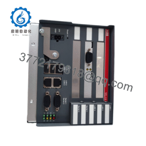
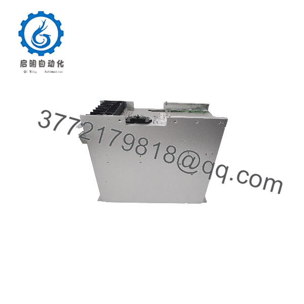
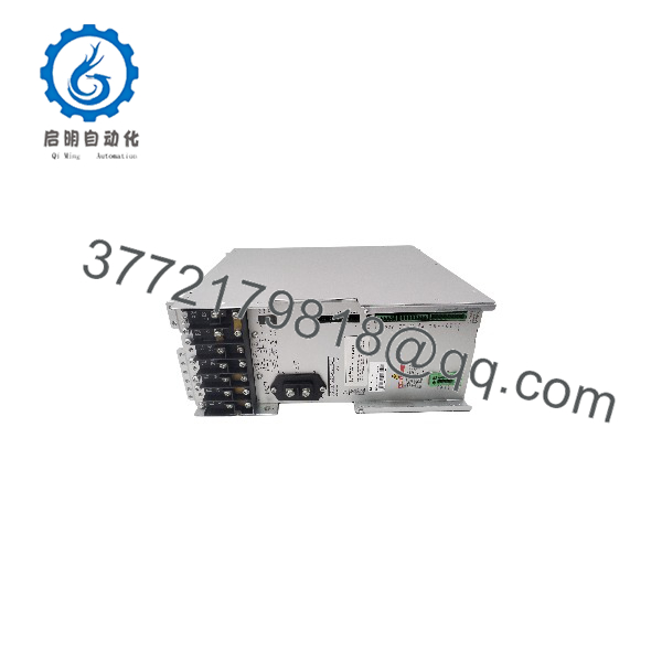
The Rexroth Indramat TVD1.3-15-03 is a non-regenerative power supply module engineered for the Indramat modular AC drive ecosystem. Operating from a direct 3-phase AC line connection of 380 V to 480 V (±10%) at 50/60 Hz without requiring an isolation transformer, the module rectifies AC mains power into a regulated 320 V DC bus voltage. It supplies continuous power to multiple downstream drive controllers and servo drives up to a continuous output rating of 15 kW.
Designed for cabinet integration within industrial motion systems, the TVD1.3-15-03 features a built-in bleeder circuit (dynamic braking resistor) to dissipate energy generated during drive deceleration. The unit incorporates extensive signal monitoring and status reporting contacts, establishing DC bus power, control voltage outputs, and protective isolation for the modular drive assembly.
Key Technical Specifications
| Parameter | Specification |
| Manufacturer | Rexroth Indramat (Bosch Rexroth) |
| Model / Type Code | TVD1.3-15-03 |
| Product Type | Non-Regenerative AC/DC Drive Power Supply Module |
| Mains Input Voltage | 3 × AC 380 V to 480 V (±10%) |
| Mains Input Frequency | 50 to 60 Hz |
| DC Bus Output Voltage | 320 V DC (±5%) |
| Continuous DC Bus Power | 15 kW |
| Peak DC Bus Power (0.3 s) | 45 kW |
| Continuous Bleeder Power | 1 kW |
| Peak Bleeder Power | 40 kW |
| Diagnostic Interface | Front-panel status LED array (Power, Mains, Faults, Control Voltages) |
| Cooling Method | Forced air / internal heatsink blower |
Detailed Product Overview
The Rexroth Indramat TVD1.3-15-03 acts as the central power supply unit for modular drive configurations, powering servo drives and main spindle drives in automated machinery. It rectifies 3-phase AC utility voltage into a controlled 320 V DC bus to feed connected drive amplifiers while simultaneously generating control electronics supply voltages (+24 V, ±15 V).
Direct Mains Operation & Power Conversion
The module connects directly to 380–480 V AC industrial mains networks, eliminating the cost, weight, and space requirements of a main supply transformer. To suppress line harmonics and satisfy EMC directives, the TVD1.3-15-03 operates in conjunction with an external commutation choke or a dedicated NAM 1.3 mains connection module.
Energy Dissipation & System Monitoring
Because the TVD1.3-15-03 is a non-regenerative power supply, kinetic energy fed back from motor deceleration is directed into the unit’s internal dynamic braking resistor (bleeder) or routed to an optional external TBM bleeder module. Integrated protection logic monitors DC overvoltage, overcurrent, heatsink thermal limits, and phase loss, automatically opening the internal contactor control circuit to isolate the drive rack if a fault threshold is reached.
TVD1.3-15-03
TVD1.3-15-03
Engineering Selection Highlights
- Direct 380–480 V AC Input: Operates without an input matching transformer across standard global industrial grid voltages.
- 15 kW Continuous / 45 kW Peak Capacity: Delivers high acceleration reserve power for dynamic multi-axis feed and spindle drive applications.
- Integrated Bleeder Circuit: Features a 1 kW continuous (40 kW peak) braking resistor to handle motor deceleration energy without additional hardware in standard configurations.
- Centralized Drive Bus Power: Supplies regulated 320 V DC bus power and control signal voltages across the backplane to all adjacent drives.
- Comprehensive Visual Diagnostics: Front-panel LED displays isolate power faults, thermal pre-warnings, overcurrent, and DC bus overvoltage conditions for rapid maintenance response.
System Compatibility & Integration Requirements
| Item / Dependency | Verified Compatibility or Requirement | Practical Note |
| Drive Ecosystem | Indramat Modular AC Drive Systems (DDS, KDS, TDM, RAC series) | Connects to adjacent drive amplifiers using bus bar links and ribbon control cables. |
| Mains Adaption Module | Indramat NAM 1.3 (or individual commutation choke KD / GLD) | Required to suppress system line perturbations and meet industrial EMC standards. |
| Bleeder Expansion | Indramat TBM 1.2 or External Bleeder Resistor | Recommended when system regenerative braking energy exceeds the internal 1 kW continuous limit. |
| Capacitance Module | Indramat CZ 1.2 / TCM 1.1 Bus Capacitance Modules | Can be added to the DC bus to store braking energy or smooth heavy acceleration spikes. |
Dimensions, Mounting & Connection Notes
- Cabinet Mounting: Install vertically within an IP54-rated control enclosure. Maintain specified vertical clearance above and below the module to facilitate passive and forced convection airflow.
- DC Bus Connections: Connect DC bus copper bars (L+ and L-) securely across adjacent drive units. Tighten terminal connections to specified torque values to prevent high-resistance contact points.
- Grounding (PE): Connect a heavy-duty protective earth ground conductor directly to the module earth terminal before energizing power circuit connections.
- Control Signal Wiring: Plug-in terminal blocks accept control and status monitoring lines. Shielded wiring must be used for signal exchange to prevent noise coupling.
FAQ
What is the primary function of the Rexroth Indramat TVD1.3-15-03?
The TVD1.3-15-03 rectifies 3-phase AC mains voltage into a regulated 320 V DC bus to supply power to Indramat modular servo and spindle drive systems.
Does the TVD1.3-15-03 feed energy back into the power grid during motor braking?
No. The TVD1.3-15-03 is a non-regenerative power supply module. Regenerated energy from motor deceleration is converted into heat via an internal or external bleeder resistor.
What AC mains voltage range is compatible with the TVD1.3-15-03?
The module accepts a 3-phase AC input voltage between 380 V and 480 V (±10%) at 50/60 Hz without requiring a mains transformer.
Which additional components are typically installed alongside the TVD1.3-15-03?
A typical installation uses an NAM 1.3 mains connection module (or individual commutation chokes), along with optional TBM bleeder modules or CZ capacitor units if higher regeneration or energy storage capacity is needed.
Verification & Troubleshooting Notes
High Voltage Residual Energy Hazard
Risk of severe electrical shock. High voltage remains on the DC bus capacitors after powering off. Wait at least 5 minutes and verify that the DC bus voltage between L+ and L- has dropped below 50 V before touching connections or opening the cabinet.
1.Check Diagnostic LED Indicators:Visual Diagnosis.
Inspect the front-panel status array. Verify green LEDs for control voltages (+24V/±15V), MAINS, POWER, and Bb1 (ready relay).
Verification: All green LEDs remain solid, and no red fault LEDs (I-FAULT, P-FAULT, T-FAULT, U-FAULT) are illuminated.
2.Verify Input Line Voltages:Mains Check.
Measure phase-to-phase AC voltages across terminals L1, L2, and L3 on the mains input side using a calibrated digital multimeter.
Verification: Reading shows a balanced 3-phase voltage between 342 V AC and 528 V AC (380–480 V ±10%).
3.Measure DC Bus Output:Bus Voltage Check.
With the mains contactor energized, measure DC voltage across terminals L+ and L-.
Verification: Meter indicates approximately 320 V DC (±5%).
4.Diagnose Red Fault LED Illuminations:Fault Resolution.
Address specific fault signals based on the active indicator:
- U-FAULT (Red): Indicates DC bus overvoltage. Verify bleeder circuit integrity or add external bleeder capacity.
- T-FAULT (Red): Indicates heatsink overtemperature. Check cooling fan operation and clean internal heatsink fins.
- I-FAULT (Red): Indicates power section overcurrent. Check connected drives and motor cables for phase-to-phase or phase-to-ground short circuits.
- P-FAULT (Red): Indicates bleeder overload. Reduce axis deceleration rates or install a TBM bleeder expansion module.