WhatsApp: +86 16626708626
 Email:
 Phone: +86 16626708626
Description
Core Product Summary
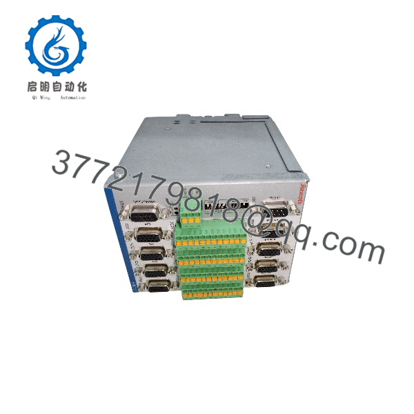
The Bosch Rexroth VT-HNC100-4-3X/P-I-00/G04 is a programmable digital axis control in the VT-HNC100 3X product family, configured as the four-axis version. It is a dedicated NC control for closed-loop electro-hydraulic motion: it executes positioning, pressure and force control, differential pressure control, axis synchronization, and cam functions, and it generates the command signals for proportional and servo valves in hydraulic motion systems.
The “/P” designation identifies the PROFIBUS DP bus version, allowing the control to be integrated into a higher-level automation system as a bus slave. Feedback is accepted from incremental encoders and SSI position transducers. Application data sets are created on a PC with the WIN-PED operating software and transferred over an integrated RS-232 interface or optionally via TCP/IP. The unit mounts on a top-hat rail inside the control cabinet and operates from a 24 V DC supply (18–30 V permissible range) with a current draw of approximately 4 A.
Key Technical Specifications
| Parameter | Specification |
|---|---|
| Product type | Programmable digital axis control (NC control) for electro-hydraulic axes |
| Series / version | VT-HNC100 product family, 3X series, 4-axis version |
| Material number | R901134617 |
| Number of controlled axes | Up to 4 electro-hydraulic axes |
| Bus system | PROFIBUS DP |
| Position feedback | Incremental encoder and SSI transducer interfaces |
| Processor | 32-bit Power PC microprocessor |
| Programming software | WIN-PED 6 / WIN-PED 7 |
| PC interface | Integrated RS-232 serial interface; TCP/IP optional |
| Supply voltage | 24 V DC nominal; 18–30 V DC permissible range |
| Current draw | Approx. 4 A at 24 V DC |
| Encoder supply | ‘+5 V / +24 V transducer supply (24 Venc connections per slot) |
| Mounting | Top-hat rail (DIN rail) installation in control cabinet |
| Protection class | IP20 |
Engineering Selection Highlights
- Four-axis configuration: The “-4-” position in the type code identifies the four-axis version of the VT-HNC100 3X family. Selectors replacing a 1-, 2-, or 3-axis unit must verify the axis count in the full order code, since the hardware differs between versions.
- PROFIBUS DP integration: The “/P” version communicates over PROFIBUS DP, so the host PLC or master system must provide a PROFIBUS DP network and the corresponding slave configuration before the control can exchange process data.
- Feedback interface: Each axis slot accepts incremental encoder or SSI position transducer signals, with 24 V encoder supply available from the unit. Existing cylinder and valve feedback hardware should be checked for compatibility with these input types.
- Software dependency: Commissioning and parameterization require WIN-PED 6 or WIN-PED 7 running on a Windows PC, connected via the integrated RS-232 interface or optionally via TCP/IP. Without this tool, application data sets cannot be created or loaded.
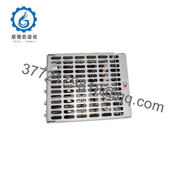
- Cabinet mounting only: The housing is designed for top-hat rail installation inside a control cabinet at IP20. The perforated housing means dirt and fluids can cause failures if the unit is exposed outside a cabinet environment.
- Power supply sizing: At approximately 4 A on 24 V DC (18–30 V permissible), the 24 V supply and its protective devices must be dimensioned for this load, including any externally supplied 24 V encoders.
VT-HNC100-4-3X/P-I-00/G04
VT-HNC100-4-3X/P-I-00/G04
System Compatibility & Integration Requirements
| Item / Dependency | Verified Compatibility or Requirement | Practical Note |
|---|---|---|
| Controlled axes | 4 electro-hydraulic axes (valves with position, pressure, or force feedback) | Axis-specific data sets define the closed-loop structure per axis |
| Bus system | PROFIBUS DP | Bus version is fixed by the “/P” order code; other family versions use CANopen or PROFINET RT |
| Position feedback | Incremental encoder and SSI transducer inputs per axis slot | Encoder supply voltage must match transducer requirements |
| Commissioning software | WIN-PED 6 or WIN-PED 7 on Windows PC | Required for creating and loading application data sets |
| PC connection | Integrated RS-232; TCP/IP optional | Connection type must be selected when preparing the project transfer |
| Mounting | Top-hat rail, control cabinet | Housing is perforated; cabinet environment required |
| Power supply | 24 V DC nominal, 18–30 V DC range | Also feeds external 24 V encoder supply via X1S |
| Connectors | Mating connector for X1S supplied; further connectors and breakout cables available as separately ordered accessories | Verify accessory order numbers before installation |
Dimensions, Mounting & Connection Notes
- The VT-HNC100…3X mounts on a top-hat rail: the rear of the housing is engaged on the rail and checked for a secure seat; the elastic rear wall provides the mechanical contact to the rail and, through it, to the cabinet back wall.
- Cable shields of the connected encoders and analog signals are connected to the housing via the shield pin of the Micro-Combicon connectors; the housing and DIN rail establish the connection to the cabinet back wall for the shielding system.
- When supplying a 24 V encoder, the input voltage at the X1S supply connector must meet the encoder’s requirements (for example, 24 V ±5 %, residual ripple below 500 mV).
- Pre-assembled breakout cables are available for the X8M encoder interfaces and the X2A analog I/O; maximum recommended breakout cable length is 2 m, and all wires on the breakout side must be terminated at the terminal strip to avoid short-circuit risk.
- The delivery includes the control unit and the mating connector for X1S; additional connectors and cables are recommended accessories ordered separately.
- After transport or storage in cold conditions, the unit must acclimate for several hours before power-up to prevent condensation inside the housing.
Detailed Product Overview
The Bosch Rexroth VT-HNC100-4-3X/P-I-00/G04 belongs to the 3X generation of the VT-HNC100 digital axis control family. The product line exists in versions for one to four controlled electro-hydraulic axes, and this order code identifies the four-axis configuration. The controller is a programmable NC control specifically engineered for the closed-loop control of hydraulic drives, which distinguishes it from general-purpose PLC-based motion: the control structure, input conditioning, and diagnostic functions are tailored to hydraulic axis behavior.
Functionally, the unit combines four closed-loop axis channels with a sequence-level programming environment. Technology functions available on the platform include positioning, pressure and force control, differential pressure control, axis synchronization, and cam (electronic curve) operation. In practice this means a single unit can coordinate the motion of four hydraulic axes — for example, closing the loop on cylinder position during a fast approach and switching to pressure or force control during a pressing phase, or keeping two axes synchronized during transfer motion. The closed-loop output stages drive the command inputs of proportional and servo valves.
Engineering of an application follows a defined workflow. Application-specific data sets are created on a PC using the WIN-PED operating software (WIN-PED 6 or WIN-PED 7), then transferred to the controller over the integrated RS-232 serial interface or, optionally, over a TCP/IP connection. The combination of the user program and the data sets is referred to as a project. This workflow matters for maintenance planning: replacing or reconfiguring a unit requires access to the WIN-PED project files and a PC connection, so machine builders and service teams should keep project backups with the machine documentation.
The “/P” version communicates with higher-level automation systems over PROFIBUS DP. On the process side, each axis slot provides an encoder interface for incremental or SSI position transducers, and the analog I/O supports valve command outputs and feedback inputs. The 32-bit Power PC processor executes the NC program and the axis control loops. Front-panel LEDs indicate supply voltage (3.3 V), run state, and bus status, which supports first-level diagnosis during commissioning and fault finding.
Installation constraints are worth noting during cabinet layout. The unit is designed for top-hat rail mounting with IP20 protection, and its housing is perforated — the manufacturer explicitly warns that dirt and fluids entering through the perforations can cause failures, so the control must remain within a suitable cabinet environment. Shielding is handled through the connector shield pins and the housing-to-rail path, and 24 V encoder supply quality at the X1S input must match transducer specifications. These installation details, together with the exact axis count and bus type encoded in the order designation, are the decisive checks when confirming that a given HNC100 unit matches the machine into which it is to be fitted.
Applications & System Role
Within a hydraulic motion architecture, the VT-HNC100-4-3X/P-I-00/G04 sits between the machine’s supervisory control layer and the hydraulic valves: it receives motion commands, executes the closed-loop axis control in real time, and drives proportional or servo valves so that cylinders and hydraulic motors follow the commanded position, velocity, pressure, or force profiles. As a PROFIBUS DP slave, it reports axis states and accepts setpoints from a host PLC, which keeps machine sequencing in the PLC while the axis-level control loops remain in the HNC100.
The manufacturer documents the primary application ranges of the VT-HNC100…3X family as machine tools, plastics machinery, special-purpose machines, presses, and transfer systems. The technology functions — sequence programming, positioning, pressure/force control, differential pressure control, synchronization (Gleichlauf), and cams — map directly onto typical tasks in these machine classes, such as coordinated multi-cylinder motion on a press, position/pressure switchover on injection or die-camping equipment, and synchronized transfer handling.
FAQ
What is the Bosch Rexroth VT-HNC100-4-3X/P-I-00/G04?
It is a programmable digital axis control (NC control) from the Bosch Rexroth VT-HNC100 3X family, configured for the control of four electro-hydraulic axes, with material number R901134617.
What does the VT-HNC100-4-3X/P-I-00/G04 do?
It performs closed-loop motion control of hydraulic axes — positioning, velocity, pressure/force, and differential pressure control — and generates command signals for proportional and servo valves. It also supports sequence programming, axis synchronization, and cam functions.
Which bus system does this version use?
The “/P” designation identifies the PROFIBUS DP bus version, used to connect the control as a slave to a higher-level automation system. Other versions of the same product family use CANopen or PROFINET RT instead.
What position feedback does it accept?
It connects incremental encoders and SSI position transducers through the per-axis encoder interfaces, with 24 V encoder supply available from the unit.
Which software is required to program and commission it?
Commissioning is performed with the WIN-PED operating software (WIN-PED 6 or WIN-PED 7) on a Windows PC, connected via the integrated RS-232 interface or optionally via TCP/IP.
How is the unit mounted and installed?
It is installed on a top-hat rail inside a control cabinet. The housing is perforated and rated IP20, so exposure to dirt or fluids outside a cabinet can cause failures; cable shields connect via the connector shield pins to the housing and rail.
What power supply does it need?
It operates from a 24 V DC supply within an 18–30 V DC permissible range, with a current draw of approximately 4 A. When 24 V encoders are supplied from the unit, the voltage at the X1S input must meet the transducer’s requirements.
What are the documented application areas of this control family?
The manufacturer specifies machine tools, plastics machinery, special-purpose machines, presses, and transfer systems as the main operating ranges of the VT-HNC100…3X series.